OmniCal Capture
Capture is the process of projecting structured light patterns and taking images of these to later use in the calibration process.
Overview
OmniCal Capture is the process of projecting structured light patterns, taking images of these and detecting blobs within these images.
-
Define the position & properties of cameras and projectors.
-
Setup the Capture.
-
Perform the Capture.
Workflow Example
Defining cameras & projectors
-
Left click the OmniCal calibration editor from the stage editor to open it.
-
Create a new Capture Plan by right clicking the capture plan to open the capture plan manager, entering a name in the new plan field and clicking OK.
-
Right click the newly created capture plan.
-
At this point, if you wish to do a simulated capture, set Use simulated cameras to Yes.
-
Click the + icon to add each of your cameras to the plan.
-
Right click on each of the plan cameras. This will open up the Camera plan editor.
-
Left click Mobile Camera and select the required camera from the list of available cameras.
-
If you are doing a simulation, you can choose your virtual camera settings here.
-
Click the + icon to add your projectors to the plan.
Setup capture
-
Left click Setup Capture to open the Capture editor
-
Set the blob size and the grid size.
-
The blob is the size of the blobs we are projecting in pixels.
-
The grid size is the number of blobs projected horizontally.
-
Left click Grid to see how many blobs are projected, and how well they cover the surfaces you are calibrating.
-
Left click on Blobs. A test blob detection will be performed highlighted in the camera views. The colour coding of the blobs is based on the colour of the projector wireframe. The blobs should be made as small as possible, whilst still being detected in this view.
-
At this stage, you may need to adjust camera exposure for better blob detection.
-
To adjust exposure, left click on the camera name and adjust exposure time in the camera plan editor.
-
Ensure your Alignment level in the Capture setup is at a level where you can see the detail on your models clearly, as this image is the one that will be shown in Alignment.
Please note: Generally speaking, blobs should be as small as possible whilst still remaining detected by all cameras. More blobs does not necessarily mean better calibration, but will increase calibration time. 32 blobs across should be sufficient for most use cases. More blobs can be useful in a scenario where mesh deform needs to be used.
Please note: A good way of getting setting a suitable exposure time, is turning continuous capture on, selecting grid mode and adjusting the exposure time and turning continuous capture off when you are happy the blob levels are clearly visible.
Performing a capture
Warning: The stage should be clear.
Warning: No changing light levels.
Warning: No people walking across stage.
-
Click Capture from the OmniCal plan editor
-
The system will perform a capture, the time taken will depend on number of projectors & cameras and whether projectors are converging or not. For example, 4 cameras & 4 projectors non converging takes roughly a minute.
-
Verify the results of the capture by clicking View Capture.
-
Left click Blobs from the View Capture Editor.
-
Verify the blob detection results are as expected. These results should be consistent with what you saw in the capture setup. If something went wrong with the capture (change in light levels, people walking across stage), then perform the Capture process again.
Camera Diagnostics
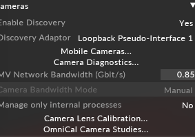
Available in the camera collapsible widget.
-
This will only be enabled if there is a plan and there are plan cameras mapped to MV cameras.
The following is shown for info:
-
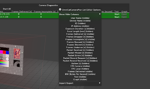
Right click header to show columns:
-
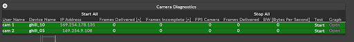
This displays camera stats and feedback of settings (such as IP, name). The disguise software only displays plan cameras.
-
Click Start Per Cam to enable stats feedback.
Visit this link for additional information about each of the specific stats.
Column descriptions
-
Frames incomplete is the only one measured by disguise and provides some feedback to the user as to the stability of the cameras in vimbacamserver.
This setting indicates that the disguise softwarefailed to validate the frame data or there may have been an exception when handling frame data from vimba api.
-
Green means cameras are ok and receiving data from vimbacamserver (with respect to the stats measuring incomplete frames between each receipt of stats).
-
Red means there have been incomplete frames between the last read and the current read.
The count of incomplete frames will continue to increase .
The red colour will reset if there have been no incomplete frames between each read of the stats.
-
Grey indicates the camera has been disabled.
-
Brown indicates the camera is disconnected/ offline.
-
Change mv camera BW to adjust bw per camera. This is split between cameras.
-
The graph button will show the stats in graph format.
-
Bandwidth allocation can be adjusted while diagnostics are running.
-
Dropped packets means you need to lower the bandwidth settings or there is a physical problem like a bad cable