IP-VFC - Implementation
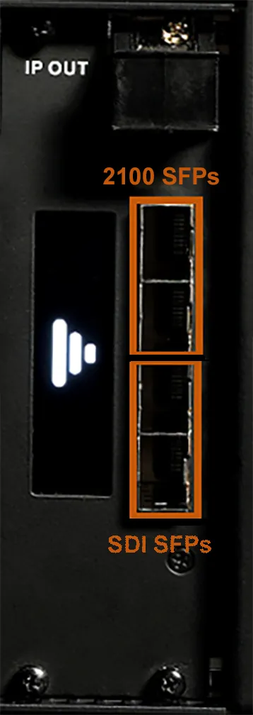
IP-VFC card looks like the below figure where the upper two ports are ST 2110 and the lower two are SDI outputs.
Users can have 4 SFPs at the same time, but will only be able to output either SDI or IP, never at the same time
Slots:
- There 4XSFP slots on a IP-VFC card.
- It supports 25G and 10G SFPs, Two IP at the top, two SDI at the bottom
- We can output either SDI or IP, never both at the same time
- For ST2110 to work the 1st eth SFP should always be present.
- Users have no control over the second SFP. d3 detects it and use it for redundant playout.
- Once inserted the first channel on the Dual SDI SFP is the lower BNC.
D3 Feed view:
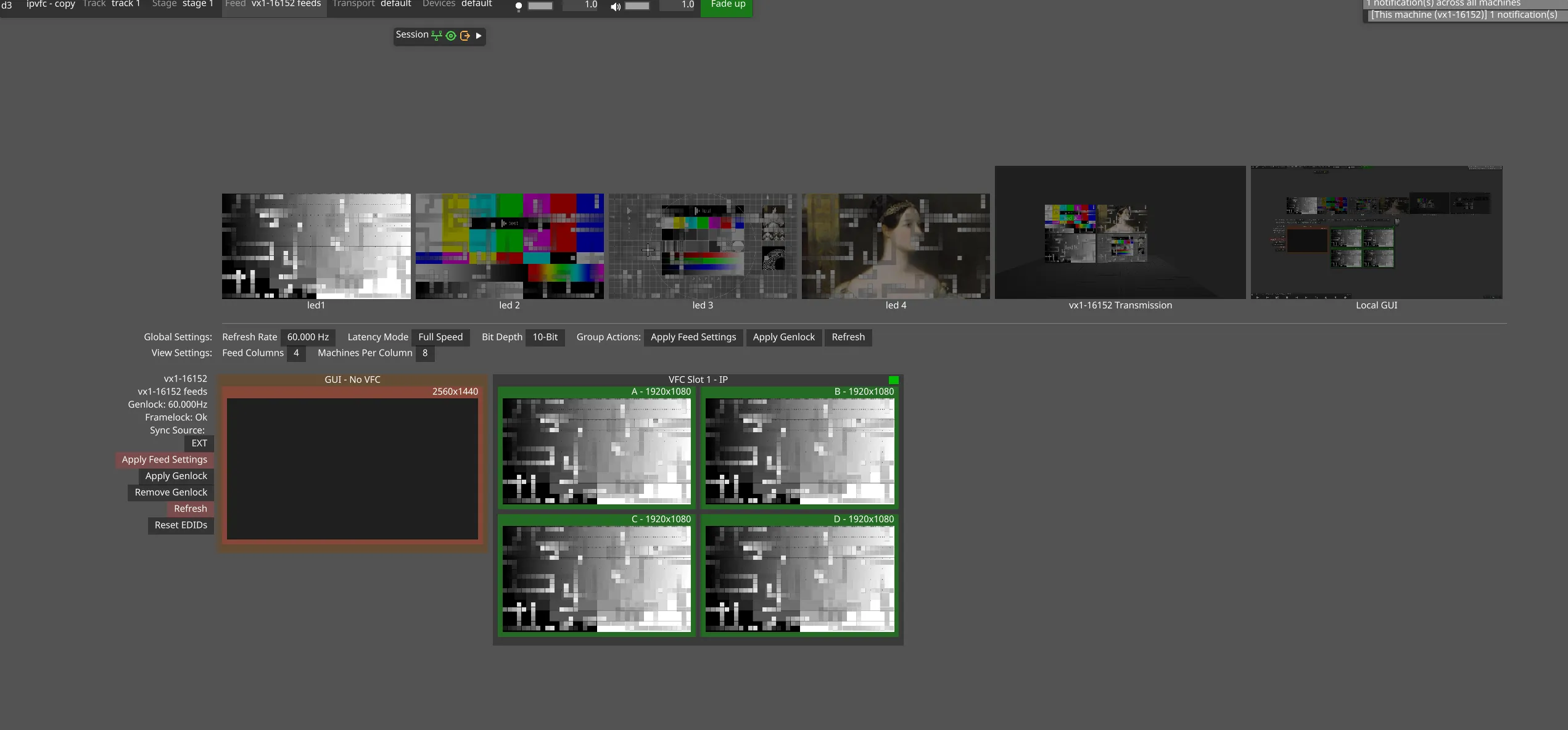
Default Quad mode view
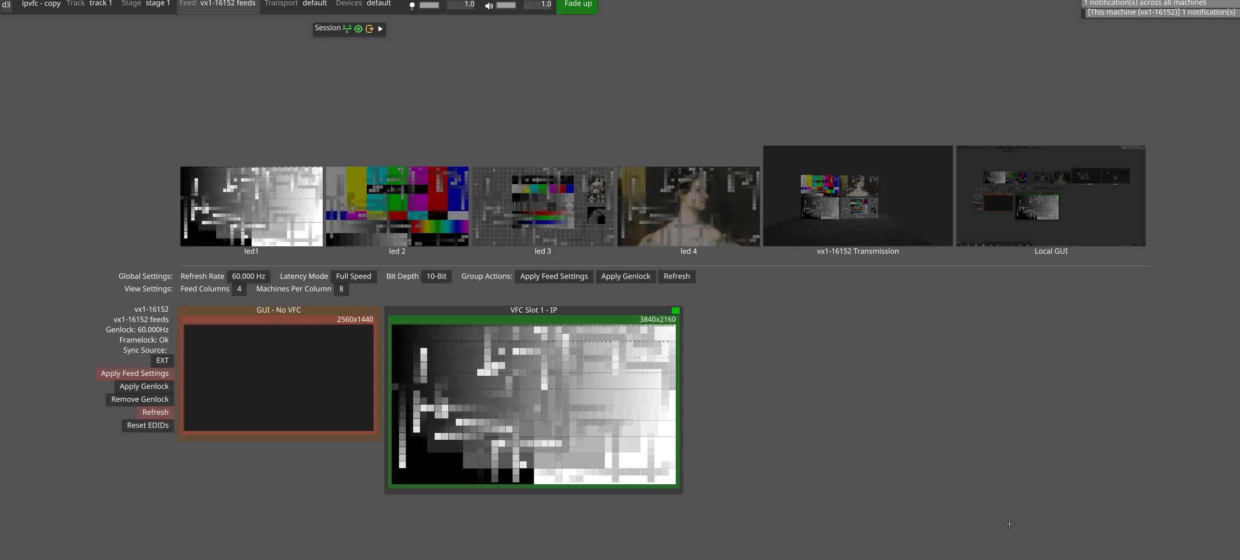
Mirror mode view
- The default view on feed window is always quad-split view.
- It supports 8 / 10 / 12 bit colour depth
- 12 bit only applicable when d3 supports it, not for testing at the moment.
- Apply feed settings is the same as always.
- If user have single IP-VFC card, feed settings will get apply only clicking on the Apply feed settings from the left grid.
Feed settings widget overview:
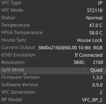
VFC card slot widget
Settings
Section titled “Settings”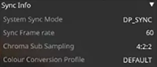
- VFC Mode:
- Native - Not a mode to use - if you see this something is probably wrong.
- ST2110 - Using the adapter in “networking” mode.
- SDI - Using the adapter in “video” mode.
- Status: The actual status of the card. This is where problems with configuration are highlighted.
- Temperature: The overall temperature of the card. If temps go towards 80c then card at risk of suddenly turning off, if this happens please note exact test setup and report to HW team.
- FPGA Temperature: FPGA stands for field-programmable gate array. Essentially, an FPGA is a hardware circuit that a user can program to carry out one or more logical operations. This is the temperature of that Chip.
- House Sync: The status of the Genlock.
- Current Output: The current resolution the raster of the card is set off.
- EDID Emulation: The status of the EDID Emulation for the card.
- Resolution: Here we can set the desired resolution for the card. -Split Mode: The way the card is set-up, can be Mirror (one single raster) or Quad (Quad Split like the DVI/SDI cards).
- Firmware Version: The firmware version of the card.
- Software Version: The software version of the card.
- VFC Generation: The generation of the card.
- Backplane Model: The backplane model of the card..
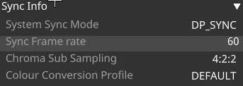
Sync info
Section titled “Sync info”1. DP_Sync Details:
-
System Sync Mode:
- PTP_LOCKED - The card is genlocked with the Grand Master Sync signal (Precision Time Protocol) and needs a PTP generator.
- EXT_SYNC - Is a special mode where the External Sync phase info is passed to the IP VFC via BP2. IP-VFC can detect how far out (or aligned) are the external sync and the output vsync of the DP signal.
-
Essentially only useful for interlaced playout so that IP-VFC can know whether to output odd field frame or even field frame
-
DP_SYNC - The card is locked to an external sync source like the usual BB or Tri-Level.
-
Sync Frame Rate: The frame rate the card is synced off
-
Chroma Sub Sampling: Colour information settings for the card
- RGB
- 4:4:4
- 4:2:2
-
Colour Conversion Profile: The colour space the card will output with
- BT.601
- BT.709
- BT.2020
- Default
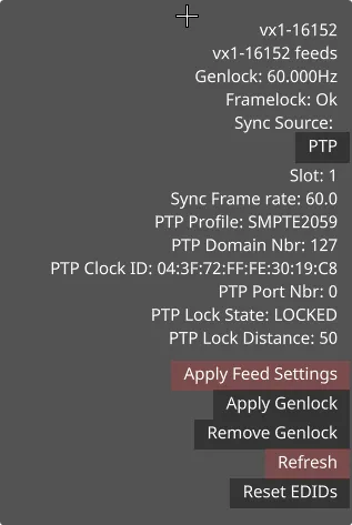
2. PTP Sync Details:
SLOT WIDGET DETAILS
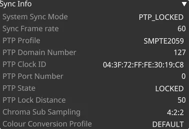
PTP Profile: The profile of the PTP in use to genlock the card (this is given by the source) by default SMPTE2059, other profiles would be special requests.
PTP Domain Number: The Domain number in use by that PTP instance. It’s a unique number, so if using multiple PTP there will be multiple instance each with their unique Domain. IPVFC settings needs to match the setting on the PTP grandmaster.
PTP Clock ID: The clock identity of the device. It is a 64-bit global identifier (EUI-64) as defined by the IEEE 1588 standard.
PTP Port Number: The number of the port in use by the PTP (319 or 320 depending by the messages).
PTP State: The status of the PTP, - “STOPPED” The PTP daemon has not yet started or was stopped for some other reason. - “FREERUN” Not locked to a PTP master and no master selected. - “UNLOCKED” Not locked to a PTPmaster but a master was selected. - “LOCKING” A PTP master was selectedand trying to lock. - “LOCKED_ns” Locked to a PTP master and perceived locking distance is within nanoseconds, where can be 500, 200, 100 or 50.
PTP Lock Distance: How ‘far’ away the grandmaster is to the IPVFC. If this value is very big IPVFC will struggle to lock to PTP, could be a problem with the network switch or if the network is large (lots of switches)
*Feed view left-PTP Sync info
-
It’s accessible also from the left-hand side of the the GUI Head in the feed view.
-
If on the side view the user has selected PTP as sync source, then during Apply Feed Settings, d3 will find the first IP VFC which is PTP_LOCKED and use this IP VFC as source of genlock for the GPU.
-
If the user has selected EXT, and if there is any number of IP VFCs which have EXT_SYNC selected then , any external sync signal will be routed to those IP-VFCs.
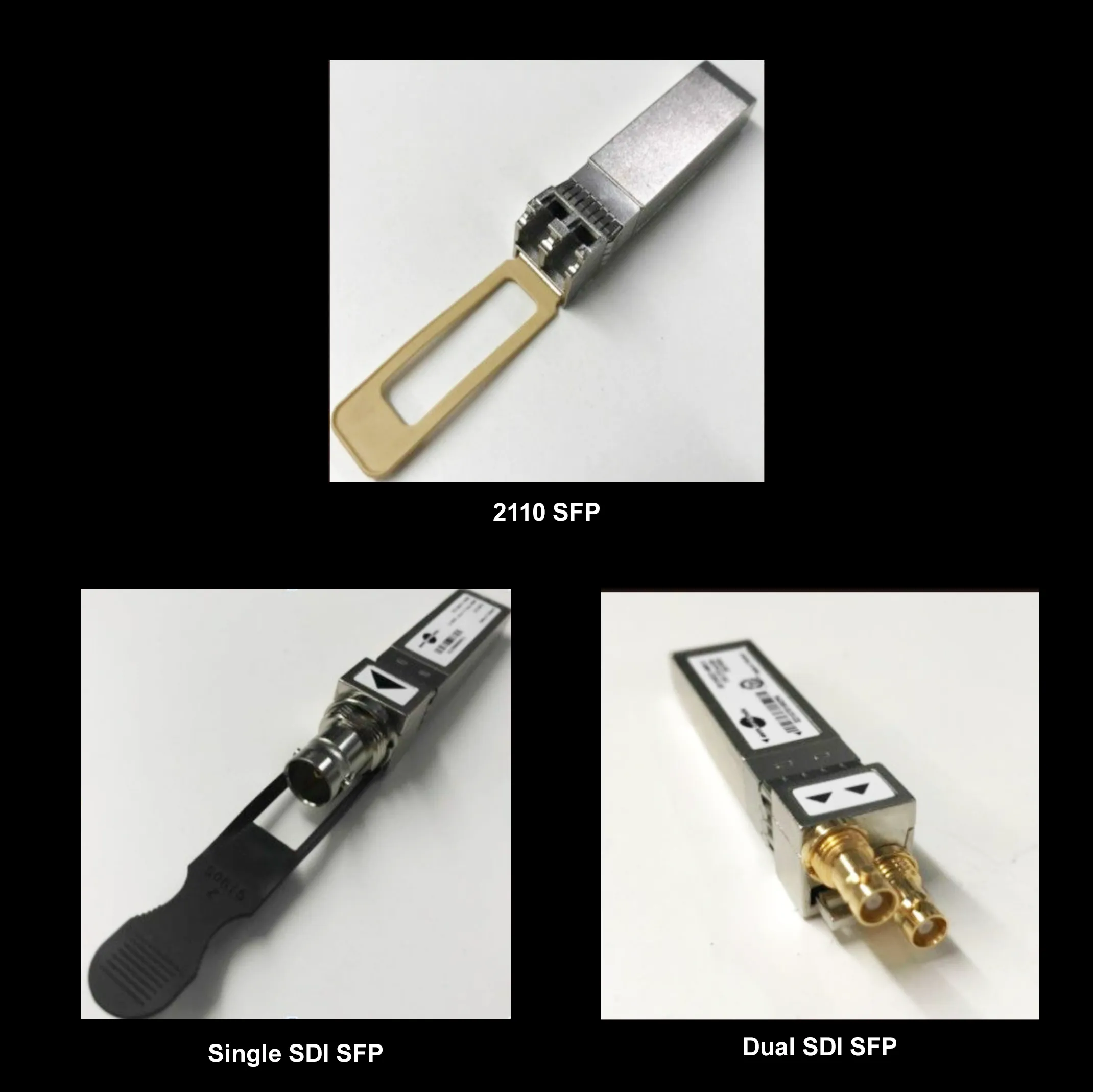
SFP Types:
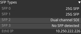
- SFP Types is the type of the adapter (SFP) that is inserted in the 4 available slots on the card. This will modify the way the signal is outputted.
- SFP 0: The first slot available from the top - Only for 2110 adapters
- SFP 1: Same as above, the second - Only for 2110 adapters
- SFP 2: the third slot - Only for SDI adapters
- SFP 3: the fourth slot - Only for SDI adapters
- The SFP can be 25G SFP - the network output, a fibre channel adapter or a dual channel SDI - the video adapter with a (HD-BNC) SDI connector on the adapter
- The slots are hot-swappable (not the VFC card itself).
Eth0 (NVM):
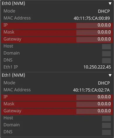
- NVM stands for Non-Volatile Memory (the opposite of the RAM)
- The card keeps the IP address that was previously set - and you need to specify all the IP for every adapter once you start the system.
Debug Properties
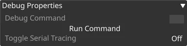
- Debug command: These options are for interacting directly with the IPVFC API. DEBUG command is the command from the Host IPVFC interfacing document.
- Toggle Serial Tracing: Toggle Serial tracing means that each API call to the IPVFC is logged in d3service.
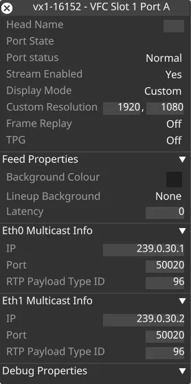
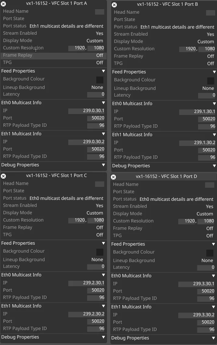
Head overview
Multi head overview
Single head overview
-
Head Name: The name of the head (Can be assigned freely).
-
Port State: The state of the port.
-
Port status: The status of the port (indicate if something doesn’t match with the rest of the project).
-
Stream Enabled: When NO indicate that there is something wrong with the output.
-
Display Mode: Right click to see settings such as interlaced output.
-
Custom Resolution: The resolution of the head.
-
Frame Replay: If set to ON, it keeps the last frame received and present that to the output.
-
TPG: Test Pattern Generator: Generates a Test Pattern internally in the FPGA.
-
Feed Properties: Same as other VFCs.
-
Eth0 Multicast Info: Multicast address, must be set differently for each feed in range 224.0.0.0 to 239.255.255.255. Always needs to be set for each stream/head
- Network info of where the content will be send to from eth0 adapter
- IP: The multicast address where to send the stream (239.x.x.x)
- Port: The port where to send the stream (Default: 50020)
- RTP Payload Type ID: The Real Time Protocol ID of the type of content is gonna be sent (96 default is Dynamic Assigned by the sender or the application that use it)
-
Eth1 Multicast Info: Network info of where the content will be send to from eth0 adapter
- IP: The multicast address where to send the stream (239.x.x.x)
- Port: The port where to send the stream (Default: 50020)
- RTP Payload Type ID: The Real Time Protocol ID of the type of content is gonna be sent (96 default is Dynamic Assigned by the sender or the application that use it).