Direct Matrix Routing
What is Direct Matrix Routing?
Section titled “What is Direct Matrix Routing?”Designer supports direct matrix routing, which sends individual routing instructions (“map input X to output Y”) to the matrix. Designer allows multiple matrix devices to be controlled, and allows fanout (a single feed output can be mapped to more than one physical output, for backup).
When a feed is assigned to a machine, Designer generates an appropriate set of routing instructions and sends this to all connected matrix devices.
Using Direct Matrix Routing
Section titled “Using Direct Matrix Routing”To set it up, you need to tell two things:
- For each machine, which matrix input each physical head connects to.
- For each feed, which matrix output(s) drive each feed head.
When a feed is assigned to a machine, Disguise generates an appropriate set of routing instructions and sends this to all connected matrix devices.
Setting up Direct Matrix Routing
Section titled “Setting up Direct Matrix Routing”- Add one or more matrix devices to your Devices list and set them up appropriately. Note that the order these devices are in the Device Manager is what defines them as Matrix 1, Matrix 2 etc. You can drag matrices up & down in the Device Manager to re-order them.
- Access your feed scene by left-clicking Feeds from the dashboard.
- Right-click the coloured border of a feed output.
- For the Matrix input & Matrix output parameter, write in a comma-separated list of (matrix number, input number),eg. “1.1,1.2” means “outputs 1 and 2 of matrix 1”.
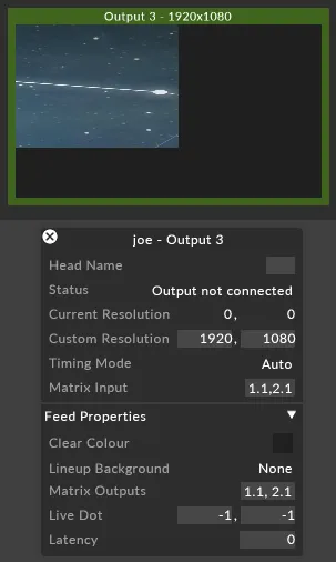
For more information on supported DVI matrices, see the Matrix switches overview.
Basic routing example
Section titled “Basic routing example”
| Machine | Routing | Routing | Routing | Routing |
|---|---|---|---|---|
| Director In | 1 | 2 | 3 | 4 |
| Director Out | 1 | 2 | 3 | 4 |
| Understudy In | 5 | 6 | 7 | 8 |
This is the easiest configuration to work with. In its most basic form, matrix routing will use a single matrix to swap the inputs on failover. This notation is as simple as typing each input and output number into the feed properties of each machine. This matrix is using a 1-to-1 routing, and on failover inputs 5-8 are used to receive from the Understudy.
Matrix DA routing example
Section titled “Matrix DA routing example”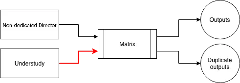
| Machine | Routing | Routing | Routing | Routing |
|---|---|---|---|---|
| Director In | 1 | 2 | 3 | 4 |
| Director Out | 1,5 | 2,6 | 3,7 | 4,8 |
| Understudy In | 5 | 6 | 7 | 8 |
In this example, each matrix output is doubled up and sending a duplicate output. In Designer the notation for this is to comma separate the output numbers. This example shows input 1 being sent to outputs 1 and 5, 2 to 2 and 6, and so on. On failover, 5 is routed to 1 and 5, etc. The comma only works in the output field of each routing
Multiple matrices routing example
Section titled “Multiple matrices routing example”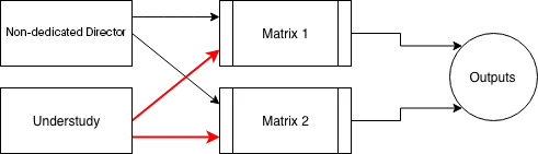
| Machine | Routing | Routing |
|---|---|---|
| Director In | 1.1 1.2 1.3 1.4 | 2.1 2.2 2.3 2.4 |
| Director Out | 1.1 1.2 1.3 1.4 | 2.1 2.2 2.3 2.4 |
| Understudy In | 1.5 1.6 1.7 1.8 | 2.5 2.6 2.7 2.8 |
This is the same 1-to-1 routing as the first example, except doubled-up. The Director and Understudy each have 8 outputs, sending 4 of each to the 2 matrices. In order to delineate between the 2 matrices, which are separate devices in the Device Manager, the above Dot notation is used. The number before the dot is the matrix’s ID, and the number after is the input or output routing number on that specific matrix. The ID number is determined by the order of the matrix-type devices in the device list, starting from the top.
Cascading matrices routing example
Section titled “Cascading matrices routing example”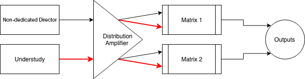
| Machine | Routing | Routing | Routing | Routing |
|---|---|---|---|---|
| Director In | 1.1 | 2.1 | 1.2 | 2.2 | 1.3 | 2.3 | 1.4 | 2.4 |
| Director Out | 1.1 |1.2 | 1.3 | 1.4 | 2.1 | 2.2 | 2.3 | 2.4 |
| Understudy In | 1.5 | 1.6 | 1.7 | 1.8 | 2.5 | 2.6 | 2.7 | 2.8 |
This more complex notation is able to send two or more commands for each input or output routing. In this example, a distribution amp or similar is doubling every signal before it reaches the matrices, so each output from Designer reaches more than one matrix at once.
The Pipe notation is able to send multiple whole commands per feed output. The order the routing is written in is important: one routing is before the pipe, the other is after. On failover, the understudy would route 1.5 to 1.1 and 2.5 to 2.1 at the same time, and so on.
Note that the Pipe operator requires a space either side of it (|), unlike other operators.
This needn’t stop at two routings per output; a second pipe can be used if a third matrix needed to be controlled (1.1 | 2.1 | 3.1). The dot notation is also in use because more than one matrix is being controlled. All three - comma, dot and pipe - can be mixed and matched to suit the exact configuration of matrices in use.