OmniCal Calibration
Calibration is the automatic process of calculating camera and projector poses and settings using the blobs detected during OmniCal Capture. Calibration also produces a consistent 3D point cloud formed from all blobs.
OmniCal Stage Plan
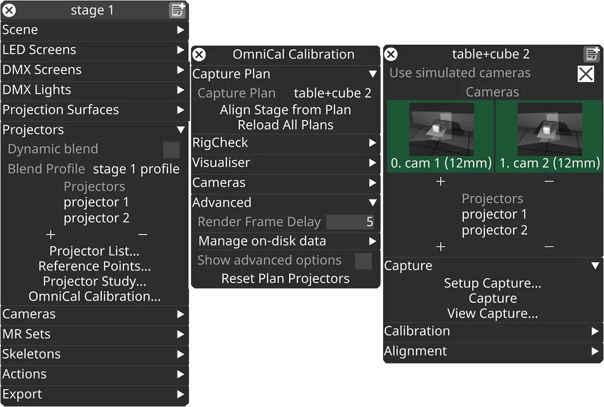
In the Stage editor, under Projectors, click OmniCal Calibration to open the Calibration editor. This widget controls the main OmniCal behaviour. Right-click on any Capture Plan to open its OmniCalStagePlan editor.
In the OmniCalStagePlan we recommend working through the sections from top to bottom: Capture, Calibration, Alignment, and Mesh Deform (if required).
Calibration
Section titled “Calibration”The calibration process triangulates the position of the blobs detected in a capture as well as the relative positions of cameras and projectors and their lens intrinsics. From this point, you no longer need access to the physical stage to continue the calibration process.
Calibration Stages
Section titled “Calibration Stages”OmniCal calibration has several stages:
- Camera Calibration
- Camera poses are calibrated based on the detected blob information and pre-calibrated lens data.
- Camera Graph Calculation
- Cameras are connected to each other on a graph, depending on their mutual overlap.
- This graph is saved in the project, and re-used in later RigChecks, to ensure that alignments remain compatible.
- Point Cloud Reconstruction
- A combined point cloud is generated from all blobs seen by all camera pairs.
- Projector Calibration
- Projector poses and intrinsics are calibrated using the point cloud and projected blob coordinates.
- Bundle Adjustment
- An iterative process that optimises the pose and intrinsics for all cameras and projectors by minimising the total reprojection error.
- Final Point Cloud Reconstruction
Calibration Settings
Section titled “Calibration Settings”Click Setup Calibration… to open the OmniCal Calibration Setup widget.
In most cases, the default settings suffice. If calibration results are unsatisfactory despite good capture quality, adjust one setting at a time to clearly assess its impact.
By default more advanced calibration settings are hidden. Enable the checkbox Show Advanced Options to see all available settings.
Redo Blob Detection
Section titled “Redo Blob Detection”If Redo Blob Detection is enabled, then pressing Calibrate will first re-run the blob detection steps, before proceeding with the normal calibration.
Blob detection is always run as part of the OmniCal capture, which then saves the blob data to disk. Calibration usually loads this blob data at the beginning of a new calibration process.
Re-running blob detection allows users to adjust certain limits in the Blob Detection Settings in Capture Setup, so that they take an effect during the next calibration. Only blob filter settings like Blob Area Limits etc have an effect in this workflow. Settings related to blob projection (like Blob Size) are fixed, since this would require re-running a full capture.
Adjusting the Blob limits and then re-running the Blob detection can be a useful troubleshooting step, especially if:
- not enough blobs are actually in use, due to too strict Blob limits filters.
- Loosening Blob Circularity Limits and Blob Inertia Limits prevents discarding blobs that appear elongated on the projection surface.
- Adjusting the Blob Area Limits minimum value can help include small blobs that are otherwise discarded.
- there are very large blobs that badly affect the results, or that are wrongly split into many smaller blobs. Using a smaller Blob Area Limits maximum value may help in this case.
- there are many very small blobs that badly affect the results. Using a larger Blob Area Limits minimum value may help in this case.
Camera Calibration settings
Section titled “Camera Calibration settings”The Camera Calibration separator contains settings that only affect the calibration of OmniCal cameras.
But note that the quality of the camera calibration affects the generated point cloud, and thus directly the quality of projector calibrations.
Camera Outlier Handling
Section titled “Camera Outlier Handling”The Outlier Handling option controls how the initial camera calibration deals with potentially erroneous input points (outliers). Camera outliers can be caused by external influences such as reflections, stray light, partial occlusions, etc. Outlier detection algorithms use many subsets of all input point pairs to find data that causes calibrations to deviate too much from a common consensus result. These outlier point pairs are then discarded and ignored for further processing.
The following Outlier Handling modes are available for OmniCal cameras:
- RanSaC (Random Sample And Consensus): Commonly used outlier handling algorithm.
- LMedS (Least Median of Squares): More robust algorithm compared to RanSaC, but slower. It tolerates at most 50% outliers. LMedS is the default for cameras.
The Desired Confidence option determines how LMedS or RanSaC work. The default value is 0.999, and should not be modified unless instructed by Disguise Support.
This setting is separate from the one configured for projectors, see Projector Outlier Handling.
Use Camera Lens Distortion
Section titled “Use Camera Lens Distortion”The Use Lens Distortion option determines the complexity of the non-linear lens distortion model that will be used for all OmniCal cameras. Each setting determines how many and which distortion parameters are calculated or ignored during the calibration process (and later Bundle Adjustment).
Using a lens model with two radial distortion parameters works for most use cases, as it allows modelling a combination of barrel and pincushion distortion, sometimes called mustache distortion.
This setting is separate from the one configured for projectors, see Use Projector Lens Distortion.
| Lens distortion mode | # distortion terms | Distortion Model |
|---|---|---|
| Off | 0 | None |
| radial k1 | 1 | Simple radial distortion (barrel or pincushion) |
| radial k1-2 (default) | 2 | Typical radial distortion (mix) |
| radial k1-3 | 3 | Higher order radial distortion |
| radial k1-6 | 6 | Complex radial distortion |
| radial k1 + tangential | 3 | Simple radial and tangential distortion |
| radial k1-2 + tangential | 4 | Typical radial and tangential distortion |
| radial k1-3 + tangential | 5 | Higher order radial and tangential distortion |
| radial k1-6 + tangential | 8 | Complex radial and tangential distortion |
Calibration Model
Section titled “Calibration Model”The Calibration Model can be set to one of three modes:
- Auto (default): Attempt to detect appropriate model. Only manually select another mode if ‘Auto’ fails.
- Epipolar: Used with scenes “with depth”, i.e. where blobs are not just projected on a flat surface, but are spread across 3 dimensions.
- Homography: Used with scenes where blobs are mostly projected on a flat surface, or the depth provided is very shallow (e.g. < 1cm).
Point Cloud Reconstruction settings
Section titled “Point Cloud Reconstruction settings”The Point Cloud Reconstruction separator contains settings that affect the calibration of OmniCal cameras, and how they contribute to a combined point cloud.
Camera graph optimisation
Section titled “Camera graph optimisation”Camera graph optimisation should be enabled for camera setups where all cameras overlap with each other, so that they form a closed loop, i.e. the first and last camera overlap with each other. Enabling the camera graph optimisation prevents gaps or discontinuities where the point cloud boundaries meet. This will give more consistent reconstruction and calibration results for typical setups for 360-degree projections inside of or on domes, cylinders, spheres or the walls of a room.
Camera graph BA iterations
Section titled “Camera graph BA iterations”Camera graph BA iterations controls a separate Bundle Adjustment pass for the camera graph optimisation. The default is 500, but it is rare to need more than 50 iterations. This step is much faster than later Bundle Adjustment steps that involve cameras and projectors.
Projector Calibration settings
Section titled “Projector Calibration settings”The Projector Calibration separator contains settings that only affect the calibration of projectors.
Use Projector Lens Distortion
Section titled “Use Projector Lens Distortion”The Use Lens Distortion option for projectors allows the same choices as for cameras (see Use Camera Lens Distortion), but instead applies to projector calibration.
When using some ultra-short throw projector lenses (ultra-wide angle) it may be beneficial to use a higher lens distortion setting like radial k1-3 or radial k1-2 + tangential.
Projector Outlier Handling
Section titled “Projector Outlier Handling”The Outlier Handling option controls how the projector calibration deals with potentially erroneous input points (outliers). Projector outliers are typically caused by incorrect point cloud data that managed to evade the camera outlier detection. See Camera Outlier Handling for more information.
The following Outlier Handling modes are available for projectors:
- None: Any outliers are accepted into the projector calibration. This may speed up the calibration if the input data is clean. But any unexpected outliers can lead to loss of calibration quality or even failure.
- RanSaC (Random Sample And Consensus): Commonly used outlier handling algorithm. RanSaC is the default for projectors.
Inlier percentage
Section titled “Inlier percentage”Estimated number of inliers as a percentage of all input point pairs.
Used in outlier handling algorithms such as RanSaC. The default value should not be modified unless instructed by Disguise Support.
- Unit: percentage
- Range: 0 - 1. Default: 0.8 (80%).
Sample size
Section titled “Sample size”Number of point pairs grouped together during outlier handling to form a subset of the input points.
Used in outlier handling algorithms such as RanSaC. The default value should not be modified unless instructed by Disguise Support.
- Unit: count
- Range: 6 - 1000. Default: 7.
Projector Calibration Algorithm
Section titled “Projector Calibration Algorithm”The Projector Calibration Algorithm can be set to one of three modes:
- DLT (Direct Linear Transformation): requires input data “with depth”
- Zhang: also works with input data from completely flat (planar) surfaces
- Auto (default): will try all available algorithms and select the best result.
Bundle Adjustment settings
Section titled “Bundle Adjustment settings”The Bundle Adjustment separator contains settings that affect the final optimisation of calibration parameters for OmniCal cameras and projectors.
Bundle Adjustment target
Section titled “Bundle Adjustment target”The Bundle Adjustment target can be set to one of six modes:
- None
Disable Bundle Adjustment optimisation. Useful for troubleshooting, to quickly iterate over earlier capture or calibration stages. - Cameras
Only optimise cameras, and leave projectors at their initial calibration results. Fastest, but cannot guarantee the highest quality projection results. Useful for troubleshooting. - Cameras and Projectors
Optimise cameras and projectors in a combined pass, without a separate camera optimisation. Gives accurate results for two OmniCal cameras. - Cameras then Projectors
Optimise cameras first, then cameras and projectors in a combined pass. Slowest, but gives most accurate results. - Cameras then each Projector
Optimise cameras first, then each projector in an individual pass. Faster than the other combination modes. Recommended for large number of projectors, to reduce calibration time. - Auto (default)
Automatically selects the most appropriate Camera / Projector combination, based on the number of cameras and projectors:- If two cameras are used, then Cameras and Projectors is selected.
- Otherwise Cameras then Projectors is selected.
Iterations
Section titled “Iterations”The number of iterations controls how much time is spent on iteratively improving the overall calibration result. There are two separate iterations settings, that are relevant, depending on the selected BA target:
- Iterations (combined)
- Used for Cameras and combined Cameras and/then Projectors modes.
- High values will lead to longer calibration duration, especially for large numbers of cameras and projectors.
- Default: 7 iterations.
- Iterations (individual projectors)
- Used for Cameras then each Projector mode.
- This mode is faster, so the iterations can be set much higher than for the combined modes.
- Default: 14 iterations.
Perform Calibration
Section titled “Perform Calibration”Once you have finished adjusting the Calibration Settings, click Calibrate in the Plan editor and confirm with clicking “Yes” to start the calibration process. Depending on the number of cameras and projectors, this can take from a few seconds to tens of minutes.
After starting a calibration, a new window will open that shows its progress. This window also contains detailed messages about the current calibration stage. Once the calibration has finished, you can close this progress window. The messages from the progress window are saved to the OmniCal report, for later viewing.
OmniCal Report
Section titled “OmniCal Report”The OmniCal report is useful for assessing the success and quality of a calibration, and for potential trouble-shooting.
Click Open Report to see a summary of the current Plan or RigCheck Result calibration. A new window will open which details the calibration success using the OmniCal Score and RMS reprojection errors and other metrics. The report also shows the detailed messages from the earlier calibration progress window. This includes more detailed information, in case the OmniCal score and/or RMS errors are high.
Error values below 1 pixel are considered good, and above 1px usually point to something going wrong in the process (physical setup, scene, configuration, …). In many situations an error around 1.5 pixels is still acceptable, but it is worth going through troubleshooting steps to try and minimise any potential issues.
The report values are displayed using a colour between Green and Red to better highlight problematic camera or projector errors. If everything is green, then the calibration was a success.
OmniCal Score
Section titled “OmniCal Score”The OmniCal Score is a simple way to assess and compare calibration quality between Plans or RigChecks. It was introduced in r32.4 as a “single value” measure that shows whether a calibration was successful, and how good it is.
The basis of the OmniCal Score is the rounded up aggregate projector RMS error, enhanced with penalty terms for any issues that were identified during the calibration. These added penalties make the OmniCal score more useful for identifying success than standard RMS errors, which sometimes can be low despite unrealistic calibrated parameters. While the OmniCal Score is not an RMS value itself, it uses the same open-ended range, where 0 is the theoretical best value, and a value of 1 or less is considered ideal.
The OmniCal Score contains penalty terms for issues identified during the calibration, including, but not limited to:
- Projector with high RMS error.
- Projector with invalid z-clipping values.
- Projector result is mirrored or pointing backwards.
- Projector result with non-square pixels or skewed image axes.
- Projector result with unrealistic focal length, lens shift or lens distortion coefficients.
If penalties were added to the OmniCal Score, then an alert message will highlight this to the user at the end of the calibration. The OmniCal report will then contain relevant details and reasons towards the end. Some of these problems can be avoided by changing relevant calibration settings and re-calibrating (e.g. if some projectors have unrealistic lens distortion values).
The OmniCal Score is also contained in RigCheck API responses, to make it easy for API callers to compare a result against an earlier one.
Camera Table
Section titled “Camera Table”This table lists each OmniCal camera of the current calibration against its calculated RMS error. It also shows whether the calibration resulted in square pixels, i.e. the aspect ratio for a single pixel in the camera is 1:1. Non-square camera pixels are usually the result of incorrect input data, e.g. wrong camera focal length, incorrectly scaled Feed Rects or incorrect settings in the physical projector.
Below the table is the aggregate camera RMS error, which combines all camera errors into a single value for easier comparison between different calibrations.
Projector Table
Section titled “Projector Table”This table lists each projector of the current calibration against its calculated RMS error. It also shows whether the calibration resulted in square pixels, i.e. the aspect ratio for a single pixel in the camera is 1:1. Non-square projector pixels are usually the result of incorrect input data, e.g. incorrectly scaled Feed Rects or incorrect settings in the physical projector.
Below the table is the aggregate projector RMS error, which combines all projector errors into a single value for easier comparison between different calibrations. The OmniCal Score is based on this value.
Calibration and Point Cloud visualisation
Section titled “Calibration and Point Cloud visualisation”Once calibration is complete, you can view the point cloud and pixel errors for each projector. To do so, go to the OmniCal Calibration widget and open the Visualiser section. Set the Visualisation Source to Plan and set the Visualisation Mode to All or Only Point Clouds.
The generated point cloud will now be shown in the stage visualiser.
Point Cloud Visualisation
Section titled “Point Cloud Visualisation”The Point Cloud visualisation option provides several visualisation modes that help with analysing issues such as interference from other light sources, or movement during a capture. The default and most useful mode is ProjectorReprojError, which visualises the individual reprojection errors for each projected blob after projector calibration.
| Point Cloud Visualisation | Description |
|---|---|
| Off | Disable point cloud visualisation. |
| Observations | Draw number of camera pairs that see a cloud point. The observation count affects the 3D reconstruction: Red=0 (failed), Blue=1 (OK), Green=2+ (better quality). |
| InlierScore | Draw cloud point inlier category using colours. Red: invalid or outlier, Orange: outlier, Yellow: projector calibration outlier, Blue: camera calibration outlier, Green: inlier. |
| InliersOnly | Only draw cloud points that are inliers (Blue) after applying camera calibration classifiers such as RanSaC or LMedS. |
| OutliersOnly | Only draw cloud points that are outliers (Red) after applying camera calibration classifiers such as RanSaC or LMedS. Reveals unstable points, possible scene movement, mismatched blob codes etc. |
| Deform | Draw distance of cloud points to aligned mesh (along point normal), using Mesh Deform threshold settings. |
| ProjectorInliersOnly | Only draw cloud points that are inliers (Blue) after projector calibration. |
| ProjectorOutliersOnly | Only draw cloud points that are outliers (Red) after projector calibration. |
| ProjectorReprojError | Draw cloud point reprojection errors after projector calibration. The point colour indicates the error quality between Green=good, Yellow=acceptable and Red=bad/outlier. Helps identify problematic points or projection areas. |
Point labels
Section titled “Point labels”With the Point labels option a text label can be rendered for each cloud point. The text content depends on the option value. The default value is Off.
Note that rendering cloud point labels has a significant impact on performance.
| Point labels | Description |
|---|---|
| Off | Disable point labels. |
| GridCode | Draw x, y index that corresponds to the blob in the projector grid. This can be helpful for identifying points as part of OmniCal troubleshooting. |
| ProjectorReprojError | Draw cloud point reprojection errors after projector calibration. This is a single RMS error value per point and given in pixels. Lower values are better. Values larger than 1px may indicate problems with the capture, such as light interference, movement etc., especially if they appear in clusters. |
Re-running calibrations
Section titled “Re-running calibrations”Re-run a calibration by modifying a setting and clicking Calibrate again. Note that issues introduced during image capture (lighting changes, obstructions, etc.) will require re-running Capture.
Re-running the calibration with different settings is useful:
- If the calibration quality was decent, but not yet good enough. Tweaking camera or projector calibration settings can help in some cases to get better results.
- If there were incorrect calibration settings (e.g. camera calibration was set to “Homography”, but the blobs land on non-planar surfaces).
- Simply to experiment with settings, e.g. when trouble-shooting issues.
Limitations of OmniCal
Section titled “Limitations of OmniCal”OmniCal can accurately calibrate projectors, including their particular lens distortion coefficients. Any rectilinear lens is supported, including ultra-wide-angle / ultra-short-throw lenses with throw ratios around 0.35, even if they use built-in mirrors.
However, OmniCal currently does not support fish-eye lenses.
Another minor limitation is that OmniCal cannot correct chromatic aberration in projector lenses. This is a less common phenomenon in projection (compared to photography), but it is noticeable at the corners of some ultra-short-throw lenses.