Example 4-Millenia Tower
Example 4: Millenia Tower
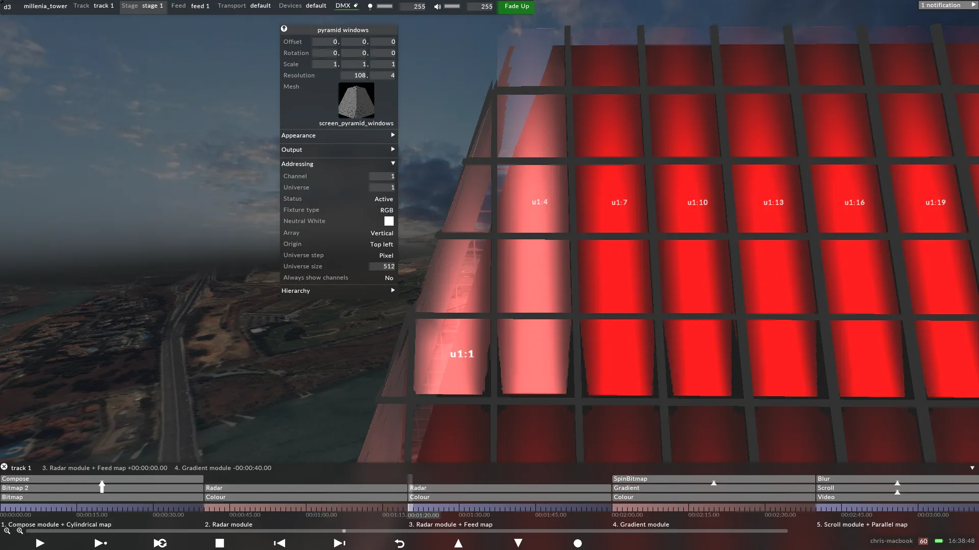
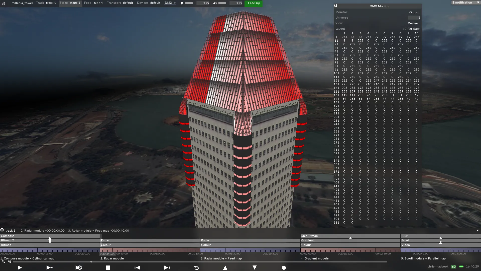
Section titled “Example 4: Millenia Tower”This case study shows how Singapore’s Millenia Tower was prepared for . The key difference here is the screens used Pulsar Chroma lights, which are DMX controlled fixtures. The previous case studies explained how to prepare DVI controlled fixtures for , although maps DMX pixels in the same way it does DVI pixels. Therefore, the 3D modelling and UV mapping techniques covered earlier apply here. However, it is important to understand ‘s DMX screen sends RGB data over Art-Net and other supported protocols, instead of the Output Feeds. To read more about DMX screens, see the Creating DMX screens sub-chapter.
How the UV map is generated
Section titled “How the UV map is generated”
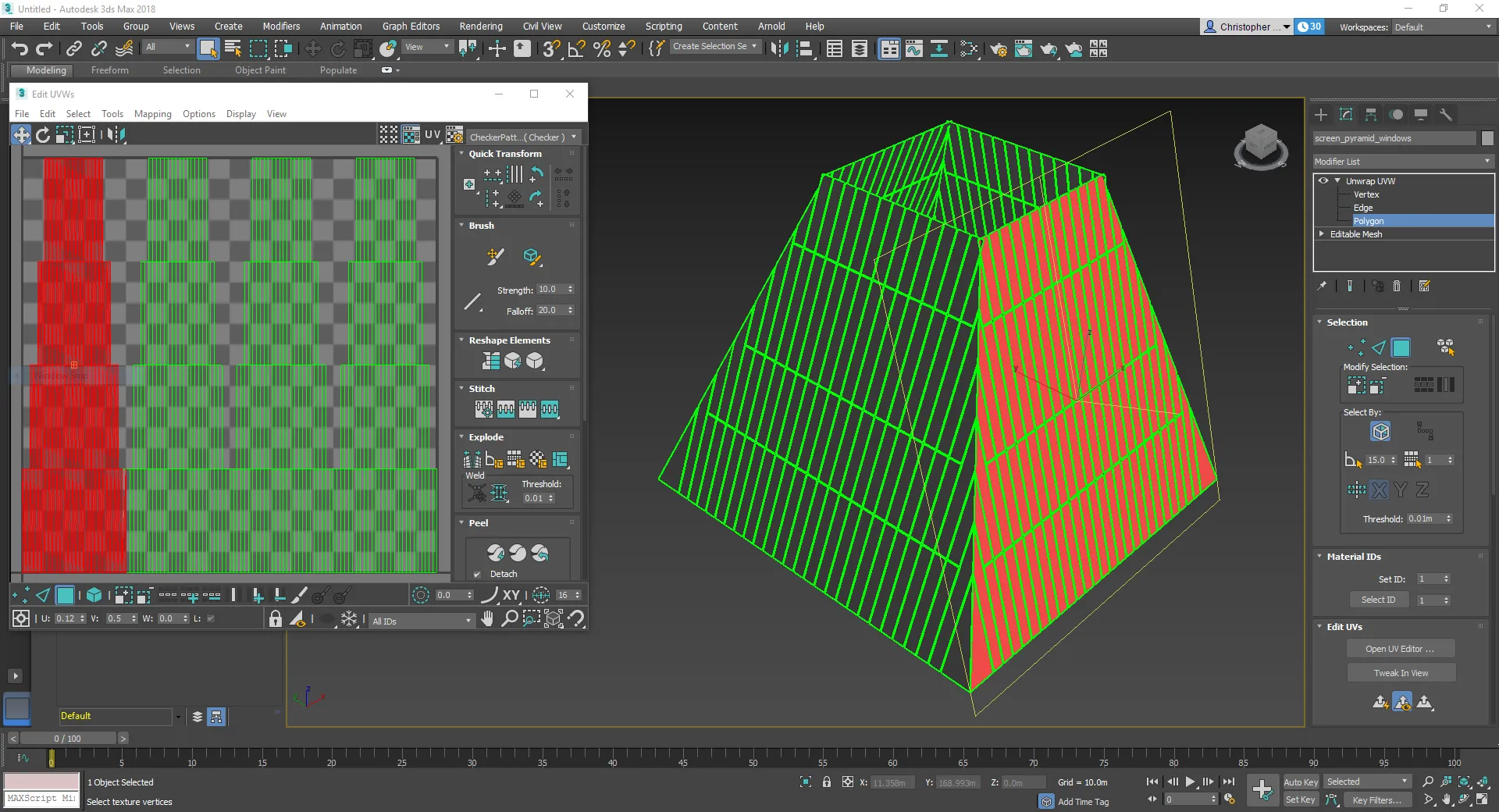
The Millenia Tower’s UV map was generated using a combination of techniques applied previously, which explained how to unwrap a 3D model into a grid.
Similar to the DNA Spiral, this UV map contains gaps separating the tower’s four sides, although in this case the 3D model does notcontain the same gaps.
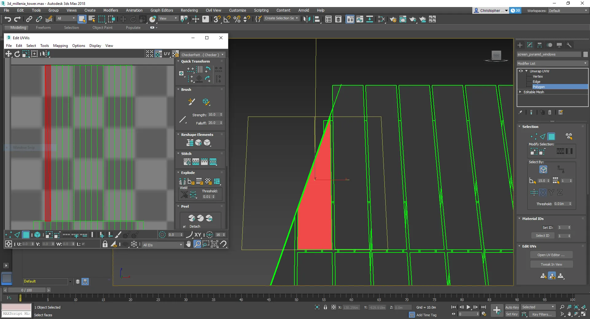
The UV map was designed on the basis that each Chroma light would be mapped in to a resolution of 1x1 pixels. Consequently, in Autodesk 3ds Max each Chroma light was assigned one UV shell, all of which matched in scale, because this ensured ‘s Direct map precisely sampled the UV map. Because the tower’s upper levels contain less Chroma lights than the lower levels, the UV map’s upper levels contained less UV shells than the lower levels, resulting in virtual gaps.


