Spatial Calibration
Here we will cover the basic steps of aligning the physical and virtual worlds within Designer for xR and VP workflows. For this guide we will focus on xR workflows because the tolerance for error is much lower in xR than in VP. The same steps are suitable for both.
A well calibrated xR stage will reveal no seams or visual artifacts that break the seamless blend between the real and virtual environments, and with adequate preparation, can be fully calibrated in less than a few hours.
Prior to beginning spatial calibration, ensure that:
- A camera tracking system is set up and receiving reliable data.
- The xR project has been configured with an MR set, accurate OBJ models of the LED screens, and tracked cameras with video inputs assigned.
- The cameras, LED processors, and all servers are receiving the same genlock signal.
- The feed outputs have been configured and confirmed working.
- The Delay Calibration has been completed.
Concepts
Section titled “Concepts”A calibration is a mathematical equation that converts from the tracking system’s coordinate space to Designer’s coordinate space. Designer will figure out this equation for you if you give it observations.
An observation is created by a set of images of the stage captured by the camera of white dots on a black background (called structured light). Designer uses the structured light to work out where the camera actually is relative to the LED surfaces. At the same time, Designer captures the position of the camera according to the tracking system. These two positions form a data point that Designer uses to create a calibration.
There are two types of observations: Primary and Secondary (P and S).
- Primary observations are used to align tracking space to Designer space. A minimum of five primary observations are required for the solving method to compute, so aim for five good observations when you begin your calibration process. Sometimes this alignment is referred to as “Registration”.
- Secondary observations are used to align zoom and focus encoder data to Designer’s lens model.
Observations are automatically marked as Primary if they have the same Zoom and Focus values as the majority of the observations.
There is no need to assign a zero point in Designer. Minimal offsets and transforms can be applied to align the tracking data and Disguise origin point prior to starting the Primary calibration, but this is not generally required.
Workflow
Section titled “Workflow”In this section we will outline the basic spatial and lens calibration workflows.
Pre-calibration setup
Section titled “Pre-calibration setup”Prior to beginning spatial calibration, ensure that:
- Your LED screens are configured with an accurate 3D model loaded in Designer. The closer your model is to real life, the better your calibration will be.
- The cameras, LED processors, and all servers are genlocked to the same signal.
- The outputs have been configured and confirmed working.
- Video receive delay has been calibrated. You can find instructions here
- A tracking system has been attached to the camera and configured both outside and inside of Designer. This is not required if you do not intend to move the camera.
- Optional: To proceed with lens calibration, a lens encoder should be attached to the lens and configured both outside and inside of Designer.
Virtual set preview setup
Section titled “Virtual set preview setup”Before calibrating, it is good practice to set up your stage to make it easy to assess the quality of your calibration.
To do this follow the following steps:
- Create a test pattern layer
- Assign a Direct mapping to this layer containing all screens that are used within the MR set being calibrated.
- Configure your feed outputs to send content to the LED screen.
- Create a virtual line up layer.
- Assign a spatial mapping set to frontplate as the mapping for this layer. This will show the representation of the virtual set and will move/deform during the calibration process.
- Right-click on the MR set widget to open it.
- Optional: Use Ctrl + left-click on the header of the editor to pin the window to the GUI.
The MR set preview will show the current active camera view, the AR Virtual Lineup overlay, and the test pattern mapped to the LED screen outputs. You’re now ready to calibrate!
Spatial Calibration Workflow
Section titled “Spatial Calibration Workflow”The spatial calibration process aligns the tracking world with the Designer world. It only uses primary observations which are automatically defined as any observations that share the most numerous pair of zoom/focus values within the list of all observations.
To carry out spatial calibration you should take the following steps:
- Open the spatial calibration editor by left-clicking spatial calibration button on the MR set.
- Ensure the correct MR set is selected and the camera being calibrated is the current target.
- Verify the camera tracking system is outputting the correct data and there is no scaling applied from the tracking source.
- Set the base/most consistent shot for the project. This is called the “hero” shot.
- Adjust zoom and focus values to their most consistently used levels for the show (If this changes later in your shoot, don’t worry, you won’t need to re-do your calibration).
- In the calibration editor, left-click Lock Zoom and Lock Focus to fix the current zoom and focus values. This will ensure that all the observations you’re taking will be marked as Primary and used for spatial calibration.
- Begin taking primary observations. Primary observations will be notated in the list with a P indicator.
- Take a minimum of 5 good observations from different camera angles/positions that will be used in the show.
- After each observation, the alignment should look good from the current camera position. If the alignment begins to fail, review all observations and remove suboptimal ones.
- Move the camera around to a representative range of positions that you expect to move it near during the shoot. If you leave a part of the room without any observations near it, the calibration the camera uses when in that region may be inaccurate.
Lens Calibration Workflow
Section titled “Lens Calibration Workflow”Lens calibration does the same thing for lens and focus data that spatial calibration does for position and rotation data. If you plan to only use a single zoom or focus setting on your lens then you don’t need to do this step at all.
Focus calibration is specifically intended to account for the problem of “lens breathing”. If you do not have this problem you can simply ignore the steps about focus calibration below.
If you do plan to use zoom and/or focus you should follow the following steps to calibrate them:
- Return the camera to a “hero” or central camera position.
- Unlock Focus.
- Adjust the focus value to the end of the range in one direction.
- Capture a Secondary observation. Secondary observations will be categorized with an S indicator.
- Repeat steps 3 and 4. Each new observation with a new focus value will create a new Lens pose. You should normally expect to use 3 observations, one at each end of the focus range, and one in the middle. If you need more you can take them but be careful not to take them too close together to avoid overfitting the curve.
- Unlock Zoom.
- Adjust the zoom by 10% of the range you expect to use.
- Lock Zoom.
- Repeat steps 3-8 until each zoom level has several focus levels captured as observations.
- Zoom the camera in and out and adjust the focus as needed. View the MR transmisison output to see if there are obvious points where the virtual zoom and focus of the stage elements do not match the real world. At those values, add more zoom and focus observations as needed.
Spatial Calibration Properties
Section titled “Spatial Calibration Properties”Here we will give an overview of all of the settings within the spatial calibration widget. Some of these are utilized in the standard workflows above and some are for more advances usage or troubleshooting.
Settings
Section titled “Settings”In this section you can configure which MR sets you want to calibrate. You can add multiple MR sets for advanced ghost-frame workflows.
Blob Settings
Section titled “Blob Settings”This allows you to configure the spacing and size of the dots displayed on the LED walls. These dots needs to be clearly detected by the camera in order for spatial calibration to give accurate results.
The optimal size and spacing of the dots generally depends on the size of the volume and the lens of the camera, so it often differs between positions based on the camera’s distance from the stage. There is no consistent range of values that works for all stages, so it is critical to find time to experiment with large and small dots to compare the results on your system.
Tips and Tricks
Section titled “Tips and Tricks”Here are some tips and tricks for setting up good blob settings:
- The default blob size and spacing is sufficient to get a good calibration in most scenarios.
- Calibration does not require that dot size and/or spacing be consistent between observations.
- Sometimes when you zoom in very close to an LED wall, the individual pixels of the LED may have visible dark-space between them which can be detected as separate blobs. This leads to poor spatial calibration. You can reduce blob size and change blob spacing to avoid this.
- You can use the observation debugging tools to look at the images captured in the observation and see if the blobs line up with reality as you expect.
Observations
Section titled “Observations”Settings under this heading allow you to take and manage observations.
It has the following options:
Use Legacy Capture
Section titled “Use Legacy Capture”This allows the user to toggle on a slower capture process which is more tolerant of dropped frames. This is not selected by default.
Pre-Calibration
Section titled “Pre-Calibration”This exposes a Capture button which will send a fixed set of colours to the LED wall in a certain order. The widget will display captured frames in order. If the images do not capture what they should (based on the description) then you are not receiving frames consistently and observations will fail to capture.
You can try the following troubleshooting steps:
- Check if you are dropping frames. Calibration will not succeed when dropping frames.
- Validate that video receive delay has not changed or drifted. You can find instructions on how to do this here
- Validate that your servers and camera are still genlocked. If they are not then observations may fail.
If you cannot solve the problem, you can try ticking Use Legacy Capture which is slower but more tolerant of frame drops and other configuration issues.
Observation Controls
Section titled “Observation Controls”Here there are two buttons:
- Add Observation - Creates a new observation
- Reset All Observations - Deletes all observations (asks for confirmation first)
Observations List
Section titled “Observations List”A list of all observations that can contribute to your spatial and lens calibrations.
The listed data for each observation includes:
- A toggle to enable and disable the observation
- The index of each individual observation.
- The tracked position of the camera when the observation was taken. (You can right-click on this to access the observation debugger)
- Zoom encoder value of the observation. (user editable)
- Focus encoder value of the observation. (user editable)
- RMS Error of the observation. This is a numeric representation of how close the observation is to the true location of the camera after calibration. Smaller values are better and you can use this to help detect outliers in your observations.
- Type of the observation: P for Primary or S for Secondary.
- A button to delete the observation.
Manual Observations
Section titled “Manual Observations”This section allows you to calibrate your camera manually for purely AR workflows. You can read more about this workflow in a guide coming soon.
Calibration
Section titled “Calibration”Adjusts global settings regarding the calibration.
-
Observations image source: Live, Write, and Read.
- Live (default): Images captured in the observation process are stored within the observation object itself and cannot be recovered if the observation is deleted.
- Write: Backs up all captures in the observation process to a newly created folder within the Windows project folder, called /debug. (Typically only used for troubleshooting)
- Read: Will read captured images from disc to recreate a calibration offline. (Typically only used for troubleshooting). When in Read mode you can also select the index of the folder you want to read from with the
Read images fromfield.
-
Adjust screen positions
- This property defines whether the calibration solver can slightly adjust screen positions while solving. You can try using this if you don’t have a very accurate 3D model to see if it improves results.
-
Detect outlier blobs
- This property is on by default and will ignore blobs that don’t fall nicely within the observation model. You can disable this for some advanced troubleshooting workflows.
-
Tracker Distortion Compensation
- This property defines how the calibration system will attempt to match the tracking system’s space to Designer’s space and which factors it is allowed to change in order to get a better calibration. In general this should be left as default unless you know something special about your tracking system. You can also experiment with different options to see if one gives you better results. The available settings are:
- None: Only accounts for the physical offsets (tracker -> focal point and tracker origin -> Disguise origin) between the tracking system and Disguise. In theory in a perfect setup this should be all you need.
- Single gain: Allows for a single scaling factor between the tracker and Disguise measurements.
- Gains: This is the default setting. It allows for different scaling factors in X/Y/Z axes.
- Gains and Skews: Also adds skews, roughly equivalent to the tracker axes not being perpendicular.
- Matrix: This is able to account for the most distortions but also is the most liable to “Over-fit” the calibration which can lead to bad extrapolated results in places outside where you’ve actively taken calibrations.
- This property defines how the calibration system will attempt to match the tracking system’s space to Designer’s space and which factors it is allowed to change in order to get a better calibration. In general this should be left as default unless you know something special about your tracking system. You can also experiment with different options to see if one gives you better results. The available settings are:
-
Calibration scope
- This property lets you define which parameters are solved for in the calibration. The available settings are:
- Lens and Registration: Optimise both the lens intrinsics and the camera-tracker registration.
- Lens Only: Optimise the lens intrinsics, take the position/rotation directly from the tracker.
- Registration Only: Optimise the registration, take lens intrinsics from the tracker (if provided) or camera.
- Lens and Manual Registration: Use regular observations to calibrate lens intrinsics and manual observations to calibrate registration.
- Registration and Focal Length: Optimise the registration and camera focal length, but not distortion parameters.
- This property lets you define which parameters are solved for in the calibration. The available settings are:
Calibration Results
Section titled “Calibration Results”Provides a list of all lens poses created by secondary observations. You can click on each one to manually edit it. This is sometimes used in advanced troubleshooting or to correct for a change in incoming data format.
Debugging
Section titled “Debugging”Following the standard calibration process correctly and consistently is very reliable and typically results in very good calibrations. Despite this, errors can and do still occur. If you are getting poor calibration results this is the section for you!
The Debugging sections offers 3 tools to help with debugging bad spatial calibrations.
- Observation Debugger - the most commonly used tool
- Plot Calibration Errors - advanced
- Show 3D Observations
Observation Debugger
Section titled “Observation Debugger”This is the tool you will most often used when debugging a bad calibration, because most of the time a bad calibration is caused by a bad observation. The observation debugger gives you options to view each individual observation to see if they are of good quality or not. You can look at each captured image to determine if the blobs were properly identified, clearly visible, and matched with the right virtual blobs. You can see if the image had a lot of light spill, reflection, poor masking, etc.
You can view Primary observations, either in “Solved” pose mode or “Tracked” pose mode. Tracked displays the values that we get from the tracker and from the camera, Solved displays the values transformed in to Designer space by the calibration and so is dependent on all the observations currently active that contribute to that calibration.
Secondary observations do not have a “Solved” mode to view because they are not used for the spatial calibration.
Troubleshooting a bad calibration with the observation debugger
Section titled “Troubleshooting a bad calibration with the observation debugger”If you have a bad calibration you will see the virtual lineup layer does not match the actual LED of the set in the background. This problem can have multiple causes, so we recommend followin this step-by-step troubleshooting guide:
-
Carry out initial checks:
- Press the ‘Re-run calibration’ button to ensure the set is in a fully calibrated state. This is especially important when re-opening or updating the project file.
- Check the primary/secondary observations are labelled as expected. It’s possible that a zoom or focus value has changed and caused them to be misinterpreted as the incorrect kind.
- Check the desired observations are enabled in the list editor.
-
Check whether the ‘solved’ results look good in the observation debugger
If not, this indicates a problem during the blob detection stage. Possible causes could be:
- Blobs have been detected in the wrong places, e.g. due to reflections. Check in the observation debugger or viewer for any detected blobs that look wrong.
- The camera moved during the observation.
- The stage model is not accurate, or the UVs are incorrect (e.g.pointing the wrong way so the screen is flipped).
- Feed output mappings are incorrect
- Check whether the ‘tracked’ results look good in the observation debugger
If not, this indicates a problem with the tracking system registration. Possible causes could be:
- The tracking system is not engaged and receiving reliable data.
- The tracking system has physically moved, or something in the setup has changed between observations.
- The tracking system coordinate system is wrong, e.g. flipped axes or incorrect rotation order. Some of the debugging tools may help diagnose this.
- The tracking system is encoder-based, and physical components are mis-measured or bending.
- Try changing the solving method of the calibration.
- If none of the above help, a normal diag with the bad observations in should be enough to look into the issue.
- If the observation debugger looks good, but Virtual Lineup layer/content looks bad, this indicates that something in tracking or registration is not being applied properly.
Possible causes could be:
- The calibration is not up to date. Press the ‘Re-run calibration’ button to be sure.
- The tracking system has physically moved, or something in the setup has changed.
- The camera has moved into a position where it is not well calibrated. Try taking another observation in this position.- The zoom/focus has changed.
-
If none of these issues are found, go through the following steps to create a project diagnostic with the information necessary for disguise support to debug the problem at HQ:
- Take an observation which shows this issue (for example, it looks fine in the observation debugger but the Virtual Lineup Layer is not aligned).
- Leave the camera in the same position that the observation was taken.
- Take a short device recording of the tracking data for the camera.- Take a screenshot of the camera feed, with the test pattern on the screens but without the Virtual Lineup Layer overlay
- Take a screenshot of the camera feed with the blob pattern preview displayed on the screens.
- Take an observation in Read mode which will write the images to the projects output folder and be included in a diagnostic.
- Export a diagnostic of the project, and along with screenshots of the MR set preview, send to support@disguise.one
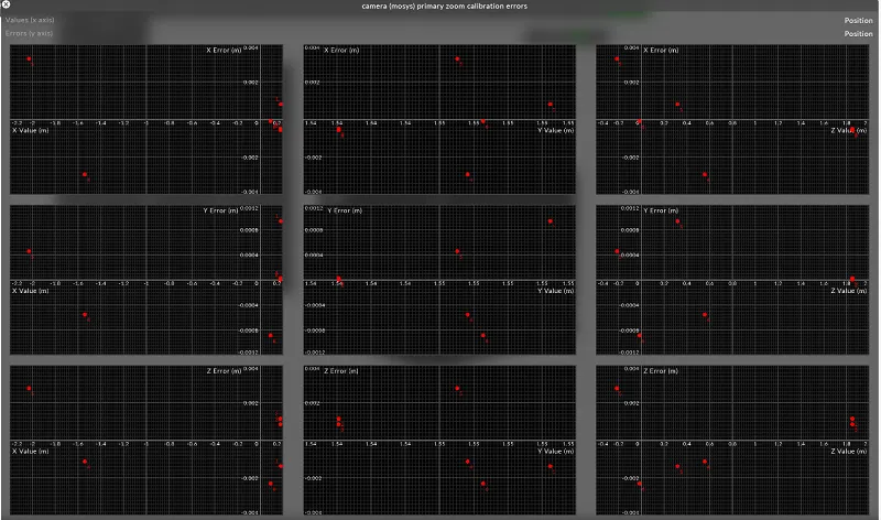
Plot Calibration Errors
Section titled “Plot Calibration Errors”This shows you plots of each spatial dimention X/Y/Z and rotations Pitch/Roll/Yaw plotted against every other dimension and rotation. This allows you to detect biases in the tracking coordinate space. You would expect each graph to look like a roughly scattered set of points with little to no correlation.
If you see an obvious pattern like a clear linear or quadratic correlation between two of the axes, this may indicate that they are unexpectedly correlated. For example, when I move the camera left and right, my tracker is also sending me movements forwards and backwards.
The Designer calibration system can account for these kinds of correlations, however this can give a very good indication of where problems within the tracking system may exist if you’re having trouble with camera moves.
An example where this might be important is a mechanical tracking system like a jib. In mechanical systems we receive tracking data based on what the motors tell us, but if the jib arm flexes as it extends, the tracking system is not aware of this flex. In this case we will see a correlation between the extension of the job arm the its vertical height which can be viewed in this debug widget.
Show 3D Observations
Section titled “Show 3D Observations”This will render 3D arrows on stage where each of the observations were taken in 3D space. This is useful if you have a part of your stage where you may have very few observations or you’re trying to take your observations in an evenly spaced manner.
It can also be useful for visualising the alignment of the tracking coordinate system with the Designer coordinate system. If there is a systematic error between the two tracking systems then you can see the areas where they align and mis-align in 3D space.