

Camera Switching
While there can only be one target camera in an MR set at any given time, an MR Set can contain multiple cameras that can be switched between using an Indirection Controller.
The target camera of an MR set determines the video input being routed to the MR set. However, multiple cameras can be added into an MR set.
Camera switching in xR requires all delays in the system to be compensated for perfectly, so that all parts of the output switch view in the same frame. This requires introducing a delay between the user requesting a switch, and the switch being visible in the output.
Controllers
Section titled “Controllers”Inside Disguise Controller we have 6 Indirection Controller Types:
- DMXIndirectionController
- ListIndirectionController
- MachineListIndirectionController
- ManualIndirectionController
- SequencedIndirectionController
- OSCIndirectionController
- UDPIndirectionController
These allow multiple protocols to be used to switch the active camera inside Disguise, as well as non-external trigger based.
Workflow
Section titled “Workflow”DMXIndirectionController
Section titled “DMXIndirectionController”This allows for Cameras to be selected in a Bank and Slot mechanism.
- Ensure you have set up Disguise to receive DMX.
- Create and assign a DMXIndirectionController to the MR Set.
- In the Sockpuppet bank editor, a Camera bank list is now made available.
- Populate banks and slots with Cameras you wish to select.
- Enter the Universe and channel you wish to select the Camera bank with into the controller.
- The slot is the next channel immediately after the bank, so you must specify 2 channels in your DMX sender.
- From the DMX sending device, send the appropriate 2 channel identifier to the universe and channel you selected.
ListIndirectionController
Section titled “ListIndirectionController”This allows for Cameras to be selected on a 0 Based index
- Create a ListIndirectionController.
- Add the Cameras as Resource.
- The order of the Cameras as the Index Number.
- Scroll through the Index to then choose the active cam.
The selected index is 0-based, meaning the first item in the list is selected by index 0.
Right-clicking on the selected index allows the user to enter an expression to control the index (e.g. allowing control from an external protocol.)
If the selected index is less than 0 or greater than or equal to the number of elements in the list, then the controller selects None as the Resource.
MachineListIndirectionController
Section titled “MachineListIndirectionController”This allows for certain machines to only output the perspective of specified cameras. A use case for this is when splitting up Front and Back plate rendering over multiple machines.
- Create a ManualIndirectionController
- Select a Camera.
SequencedIndirectionController
Section titled “SequencedIndirectionController”This is controlled by keyframes in an IndirectionControl layer. The indirection control module allows indirections to be sequenced on the timeline. One Indirection control module controls one indirection.
To sequence an indirection:
- Add a SequencedIndirectionController in the controller field of the indirection.
- Add an IndirectionControl layer to the timeline.
- Select the controller in the Indirection control module.
OSCIndirectionController
Section titled “OSCIndirectionController”This allows you to force a camera to be active over OSC.
- Create an OSCIndirectionController
- Create an OSC Device
- Add the OSC device to the Controller.
- Remove the $ sign from the OSC address field.
- The string to recall the Camera to be active is the camera’s name inside Disguise. Currently the OSC indirection controller requires you to use the full path of the object you are selecting such as:
path: /d3/indirection/osc
value: objects/camera/cam1.apx
UDPIndirectionController
Section titled “UDPIndirectionController”This allows you to force a camera to be active over UDP.
- Create a UDPIndirectionController.
- Add the number of Resources needed. This will be the number of cameras in the scene.
- Add a Key to trigger that active camera, and add a resource which would be the Virtual Camera.
- Add the receive port number from the UDP sender.
- Send the command to Disguise and see the Current Target change. Turn on Verbose Logging to check incoming strings in the console (alt+c).
Debugging Camera Switching
Section titled “Debugging Camera Switching”Clean camera switches in XR depend on the whole system being correctly calibrated, configured, and performing as expected. A switch draws on the combined accuracy of tracking, calibration, camera setup, rendering, and system timing. As a result, problems can originate anywhere in that chain.
Use this section to investigate camera switching issues and identify the most likely root cause.
Prerequisites
Section titled “Prerequisites”Camera switching has several prerequisites. Fix any that aren’t met before diagnosing further.
- The system must be fully genlocked.
- The system must not be dropping frames.
- e.g. RenderStream frame drops, camera frame drops, or tracking packet drops.
- The camera delays must be calibrated.
- Each camera must see exactly one full frame of white in the calibration widget.
- Any RenderStream assets must be running smoothly without dropping frames.
How to debug
Section titled “How to debug”Debugging can be performed using the Camera Switching Debugger. This can be accessed via:
MR set → Delay Calibration → Camera Switching Debugger.
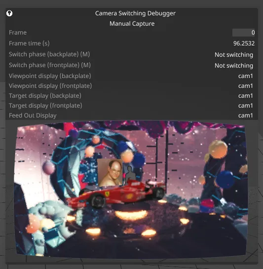
When the widget is open, it will automatically detect camera switches in the MR set and update accordingly. Change the index in the frame field to step through frames rendered around the switch. If everything is correct, you should see a clean switch between frames -1 and 0.
Module rendering vs XR compositing issues
Section titled “Module rendering vs XR compositing issues”Once the prerequisites above are met, camera switching issues fall into two areas:
- Module rendering (e.g. compensating for RenderStream latency)
- XR compositing (Syncing content between LED walls and set extension)
To diagnose which area the error is stemming from, attempt a camera switch with a single video layer mapped to the backplate. If that is clean, the issue is likely stemming from module rendering, otherwise it must be stemming from XR compositing.
Diagnosing XR compositing issues
Section titled “Diagnosing XR compositing issues”- Firstly, ensure the system is genlocked and not dropping frames.
- Use the delay calibration tool to ensure each camera’s delay is calibrated.
- While doing delay calibration, ensure each camera sees exactly one full frame of white on the screen. If not, the camera shutter settings must be adjusted until that is the case.
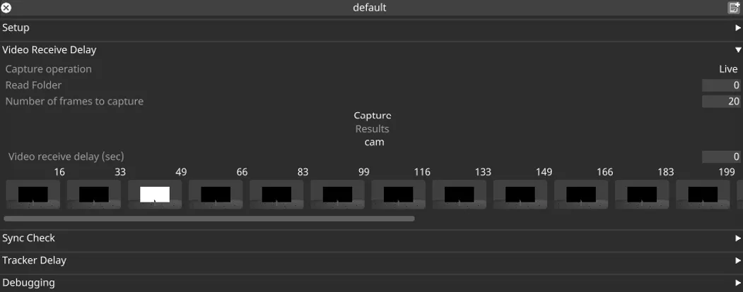
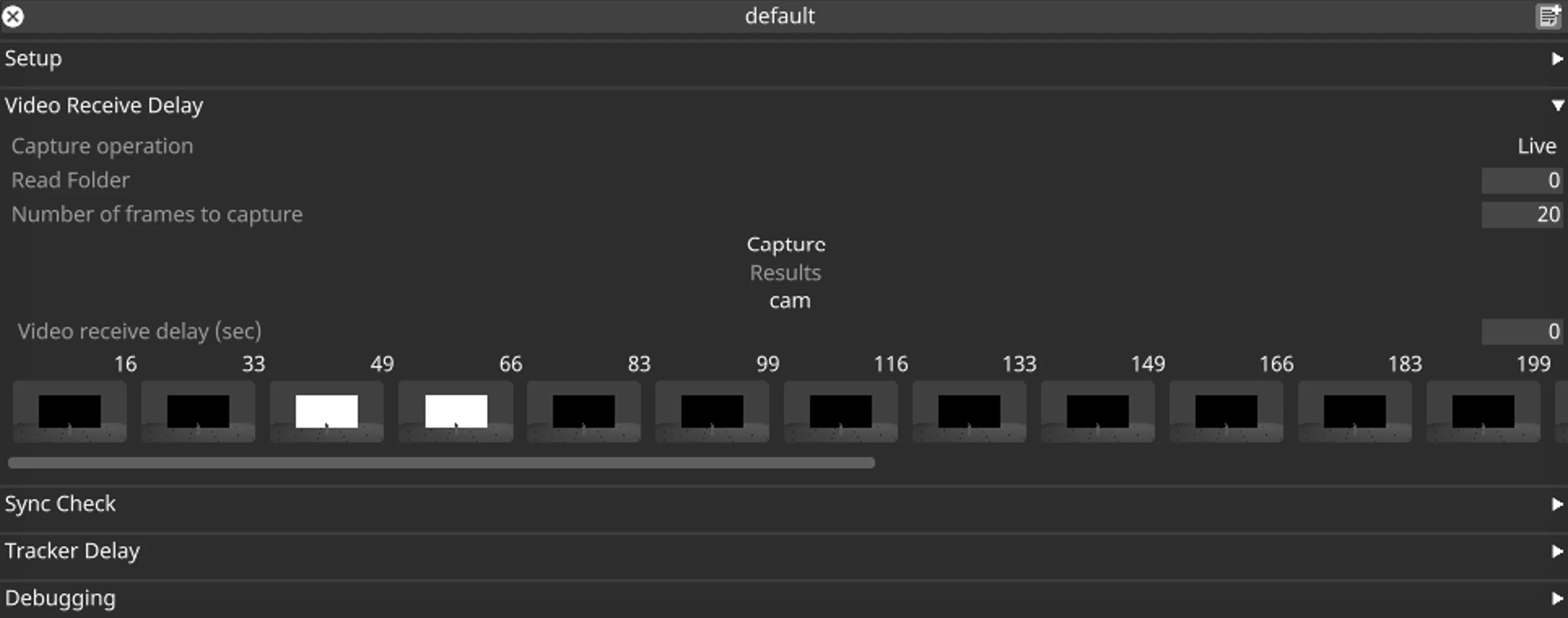
- Try using the sync check tool in the delay calibration widget.
If issues persist, then you may require assistance from support as it could be a software bug, hardware issue or a combination of the two.
If you reach this point, contact support and send a diagnostic log with the following:
- Hardware setup.
- Outcomes of the steps above.
- Frontplate reprojection mode for each camera (in particular, whether any use “Minimal Latency”).
Diagnosing module rendering issues
Section titled “Diagnosing module rendering issues”This is most likely caused by latency compensation in RenderStream modules, which you can often diagnose from the stream graphs.
View the stream graphs in the performance monitor, accessed by clicking the FPS counter in the bottom-right corner of the screen.
Stream graph
Section titled “Stream graph”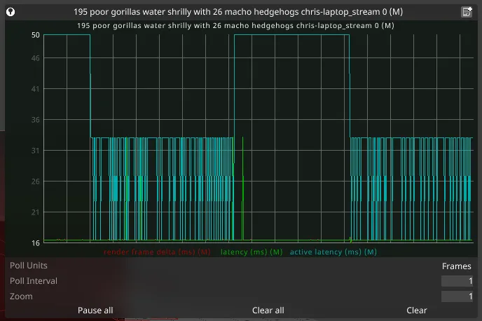
This graph tracks three separate performance metrics:
- Latency: The continuous receive latency for each frame. It should be relatively stable (doesn’t have to be perfectly flat), and not too high.
- Active latency: The total latency for the module, which includes a buffer to account for variations in the stream latency. It should be stable (unlike above) and higher than the latency value.
- Render frame delta: The difference in the receive time between each frame. It should be relatively stable, around the expected difference between render frames.
If the graph shows issues with active latency, you can set an ‘Active Latency Override’ value in the project settings. Set it to a value high enough to encompass all the expected latency spikes when looking at the graphs. You should then see the active latency being a flat line at the set value.
Render skew graph
Section titled “Render skew graph”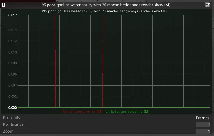
- Active latency error shows periods where the stream latency has exceeded the active latency (see above). It should be zero, otherwise you are likely to get frame drops.
- Render skew shows the difference between expected and actual times for the frame fragments retrieved from the buffer. It should be zero.
If the graphs show issues with the performance of the stream, it may be that the scene has not been sufficiently optimised. Try to reproduce with a lighter scene to see if that is the case. If issues persist even with a lighter scene, it may require a dev or support to take a look. Send a diagnostic log and include the following information:
- Hardware setup
- Images of the stream graph and render skew graph
- Do the cameras use ‘Minimal Latency’ for frontplate reprojection mode?
- Are any of the modules using non-1 frame rate fractions?