Example 1 - MiSTRIP Star
This case study shows how to prepare a star shaped LED screen constructed from Barco MiSTRIPS for Designer. The first step is to UV map the 3D model by unwrapping the mesh into a grid. As explained on The UV Map as the Hardware Output page, the UV map should comprise a grid because this is the output to the LED processor from the software, and LED processor’s can only capture outputs composed from rectangles.
How the UV map is generated
Section titled “How the UV map is generated”A plane can be arrayed around a local pivot point to recreate the surface with the UV map automatically generated. However, the UV map will have overlapping UV shells and therefore will require editing, either manually using UV editing tools or automatically using a script, depending on the level of complexity.
Step 1 - Generating the UV map (3ds Max)
Section titled “Step 1 - Generating the UV map (3ds Max)”- Draw a plane that matches a MiSTRIP’s dimensions, 0.063x1.484 metres.
- Ensure you have the box called generate mapping coordinates checked. Doing so will enable the plane to automatically generate a normalised UV map.
- Position the plane’s local pivot point to the scene’s origin. The origin is 0,0,0 in 3D space corresponding to the X,Y,Z axes.
- With the plane selected, select the Array tool.
- Array the plane by a count of 20 around 360 degrees. This will array twenty planes around the local pivot point.
- Attach all the plane’s together into one Editable Mesh / Editable Poly.
- Select theUnwrap UVWmodifier.
- Open the Edit UVWs window to view the UV map.
- At this stage, the UV map will have overlapping UV shells. To unwrap the UV map, reposition the UV shells next to each other, either manually using UV editing tools or automatically using a script.
- It is important to snap the UV shells next to each other into a grid. Doing so will remove gaps in the UV map, which in turn will remove virtual pixels from Disguise’s output to the LED processor.
- Normalise the UV map by rescaling it to fill UV space entirely from a range of 0-1 in both the U and V axes.
The image below shows the MiSTRIPs arrayed in a 360 degree arc, but in UV space they are arrayed in a horizontal row as a grid.
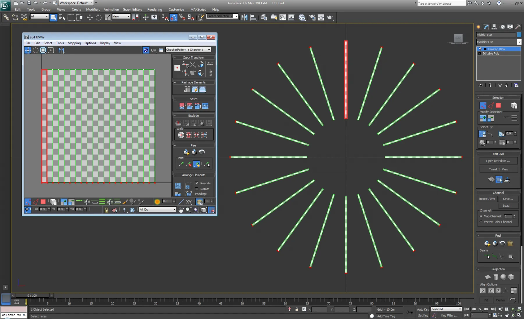
Importantly, the surface’s outer ring of vertices correspond to the UV map’s bottom row of UV coordinates, highlighted in red.
This indicates the surface’s UV coordinates are uniformly positioned.
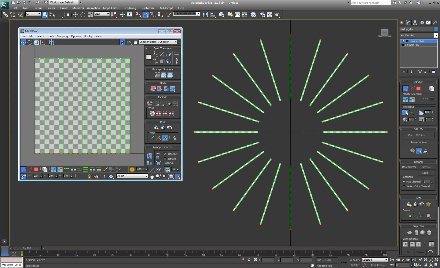
The image below shows how each MiSTRIP corresponds to a UV shell, highlighted in red. Importantly, each UV shell is equal in scale to
each MiSTRIP, which indicates the UV map has an even distribution of UV coordinates.
The image below shows how the MiSTRIPs are arrayed in UV space. Importantly, the MiSTRIPs are arrayed in a clockwise direction, and this order follows the UV map, where the UV shells are arrayed in a left to right direction.

In order to set a resolution of this screen made of 20 Mistrips it is crucial to turn each strip into a rectangle in UV space.
Step 2 - Mapping content to screens
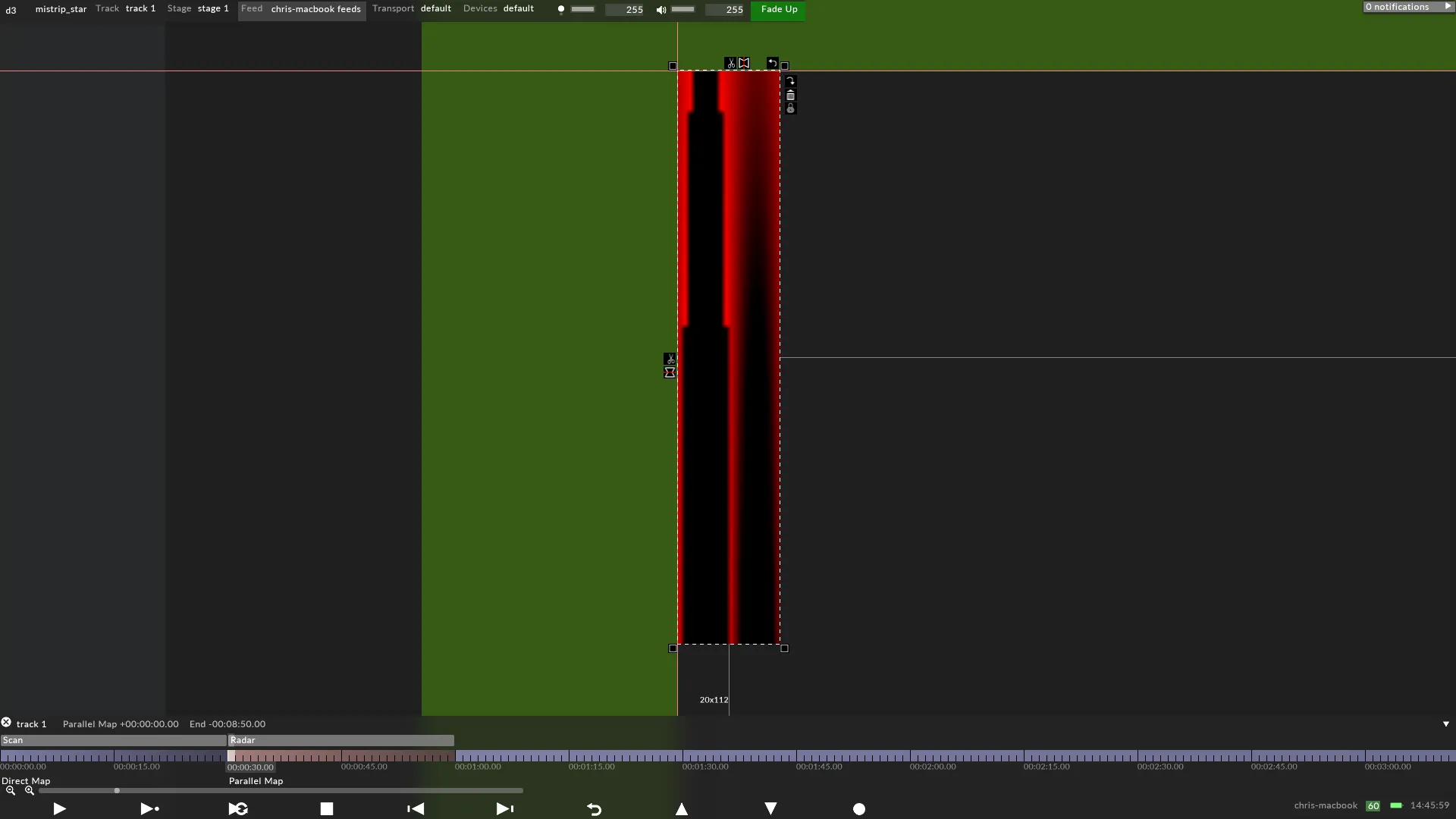
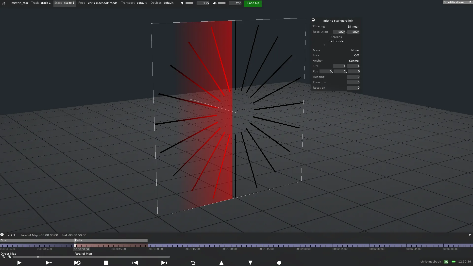
Section titled “Step 2 - Mapping content to screens”The left-image below shows a Radar layer Parallel mapped to the screen in Designer, which was exported as an .obj file from Autodesk 3ds Max. The right-image shows the Output Feed from Disguise to the LED processor, which is being generated in realtime by the Parallel map applied in Disguise’s Stage simulator. The feed output is independent of the video content, which means the output can be a different resolution. In this case, the content has a resolution of 1024x1024 pixels, but the output has a resolution of 20x112 pixels. This is possible because the Parallel map does not apply content directly to the screen’s UV coordinates; enabling the content creator to design content using templates that are independent of the LED outputs. Therefore, the creative workflow for the content creator is separated from the technical workflow for the hardware technicians, as explained on The UV Map as the Hardware Output page.
The resolution of the screen in Designer should exactly match the physical screen’s number of pixels. The resolution of 20x112 pixels was calculated by:
- Knowing precisely how many pixels each MiSTRIP contains horizontally.
- Multiplying this value by the total number of horizontal MiSTRIPs, to calculate a horizontal resolution.
- Knowing precisely how many pixels each MiSTRIP contains vertically.
In this case:
- 1 MiSTRIP = 1 pixel horizontally.
- The total number of horizontal MiSTRIPs is 20. Therefore, 1 pixel x 20 MiSTRIPs = 20 pixels horizontally in total.
- 1 MiSTRIP = 112 pixels vertically.
The UV map also represent the output sent to the physcial LED strips.
The image below shows a Population mask applied to the screen in Designer, which was exported as a .png from Adobe Photoshop. The Population mask has removed MiSTRIP sections from the screen and, in turn, from the output to the LED processor, which maybe necessary if the screen’s geometry requires updating. To read more about generating Population masks, see the Population masks page.