Manual Projector Calibration
- Open the projector editor by either right-clicking the projector directly in the Stage, or by right-clicking the projector from the screens list in the Stage Editor.
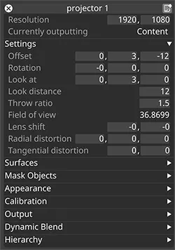
- Familiarize yourself with the properties of a projector. After this follow the instructions explained below.
Set the correct resolution
Section titled “Set the correct resolution”Set the resolution of the projector to match the corresponding output head’s resolution.
Add surfaces
Section titled “Add surfaces”Under the Surfaces tab add the projection screens that the particular projector is covering.
Add the projector outputs to the Output Feeds
Section titled “Add the projector outputs to the Output Feeds”Ensure all of the Feed rectangles from the projector outputs have been added to the output heads.
Please see adding feed rectangles for information how to do this.
Place the projector correctly
Section titled “Place the projector correctly”Change the pos (projector position) and the throw ratio (lens value) properties so that the projector covers the required part of the screen surface. A laser measure may be required to calculate the correct position by measuring the distance from the physical projector to the video surface.
Adjust the Look at position
Section titled “Adjust the Look at position”The Look at position of a projector defines the centre point of its corresponding output feed. When lining up a virtual projector to the physical projector it is therefore crucial to match the Look at position to its corresponding point in the real world.
Disguise Designer has a built-in wireframe feature allowing the system to generate a line-drawing based on the 3D mesh of the projection surface. In the same output frame Designer will also output a red cross positioned in the centre of the output feed. When the wireframe test pattern is applied, Designer will output this red cross regardless of the orientation of the projector.
Consequently, if the look at position of the projector is aligned to the red cross on the physical projection surface, the virtual projector and the physical projector are orientated around the same point which is a great starting point for an accurate manual lineup.
Align the look at position of the projector
Section titled “Align the look at position of the projector”- Change the output mode to wireframe by clicking the output tab at the bottom of the projector editor.
- Return to the Stage level. Set the step value of the look at position to 0.01 to enable smoother scrolling of the look at values. To change the step value, right-click the property name and change the value in the Step value property.
- Begin aligning the look at position of the projector to the red cross by comparing the look at positions crosshair in the Stage level and the red cross being outputted from the physical projector.

Look at position of the virtual projector now matches its corresponding point on the physical video screen, in this example a wooden sculpture.
Adjust the throw: Ratio
Section titled “Adjust the throw: Ratio”- To zoom in on the physical video screens content, change the throwRatio value. This value corresponds to the lens size of the physical projector.
- If the exact lens size is known (for example a fixed lens size is being used), type it in.
- If a zoom lens is being used, set the start value to the lowest (or highest) value in the zoom range. Slowly change the value by scrolling the mouse wheel in the property field.
Fine tune property values
Section titled “Fine tune property values”-
After setting the initial lens value, try not to edit the position properties. Instead, start adjusting the rotation parameters if needed, in particular the x and y rotations. Aim to establish parallel lines mapping onto the video screen globally rather than focusing only on one part of the screen. Adjust the step value if needed.
-
Go back and fine tune the values of the lookAt position to center the output to the physical video screen. Remember to establish parallel lines.
-
Adjust the throw ratio to zoom in/out of the content on the video screen. Assuming that the 3D mesh is accurate to the physical video screen, the mapping should gradually fall into place.
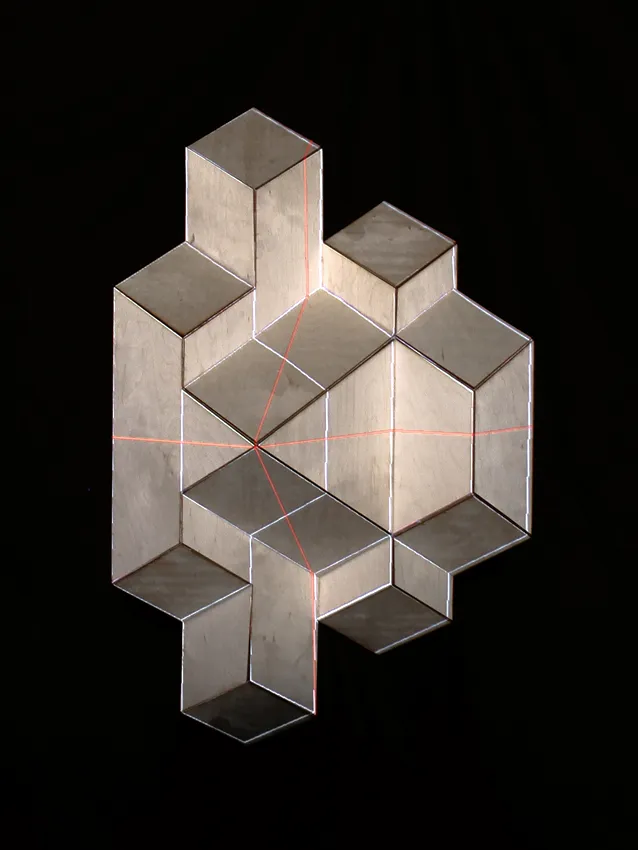
Projector has been manually calibrated; the 3D mesh test pattern now lines up with the wooden sculpture.
If the projection surface does not match the 3D model after carrying out manual calibration the lineup may need to be fine-tuned. Please see the sub-chapter Warping outputs for more information.