Getting Started
This page walks you through opening your first scene, the layout of the editor, and the basic operations you need to start designing.
Open or create a scene
Section titled “Open or create a scene”You open Mapping Matter from the Disguise Cloud launcher dashboard. The launcher has up to three tabs:
- My Projects: your organisation’s projects. Each project tile shows the plugins available on that project; clicking the Mapping Matter tile on a project opens its scene in the editor (if the project has no scene yet, Mapping Matter creates one).
- Demos: read-only demo scenes provided by Disguise.
Demo 1 - BasicthroughDemo 7 - USTcover progressively richer setups (basic projection, linear arrays, sphere mapping, textures, mesh luminance, video playback, ultra-short-throw). Click a demo tile to open it in the editor. - Migratable: only shown if you have scenes in legacy Mapping Matter. Each tile is a one-click handoff into the modern editor: the legacy scene is rebuilt as a new project with its meshes, textures and projectors carried over. The original is left untouched unless you opt in to marking it as migrated.
Project-to-scene is one-to-one: each project has exactly one Mapping Matter scene. To work on a different scene, switch projects in the launcher rather than looking for a scene picker inside Mapping Matter.
The launcher header shows a sparkle icon; open it any time to read the latest What’s New announcement from the Disguise team. An unread dot appears when a new announcement is published; the dot clears once you open the panel. Fresh sign-ins to the dashboard always pick up the latest content.
The launcher remembers your sort order (Last edited ↔ Name), scope filter (All / Private / Org / Shared), and grid/list view per browser, so the dashboard opens the same way each time. The projector and LED library overlays in the editor persist their brand filter, origin filter, and sort the same way.
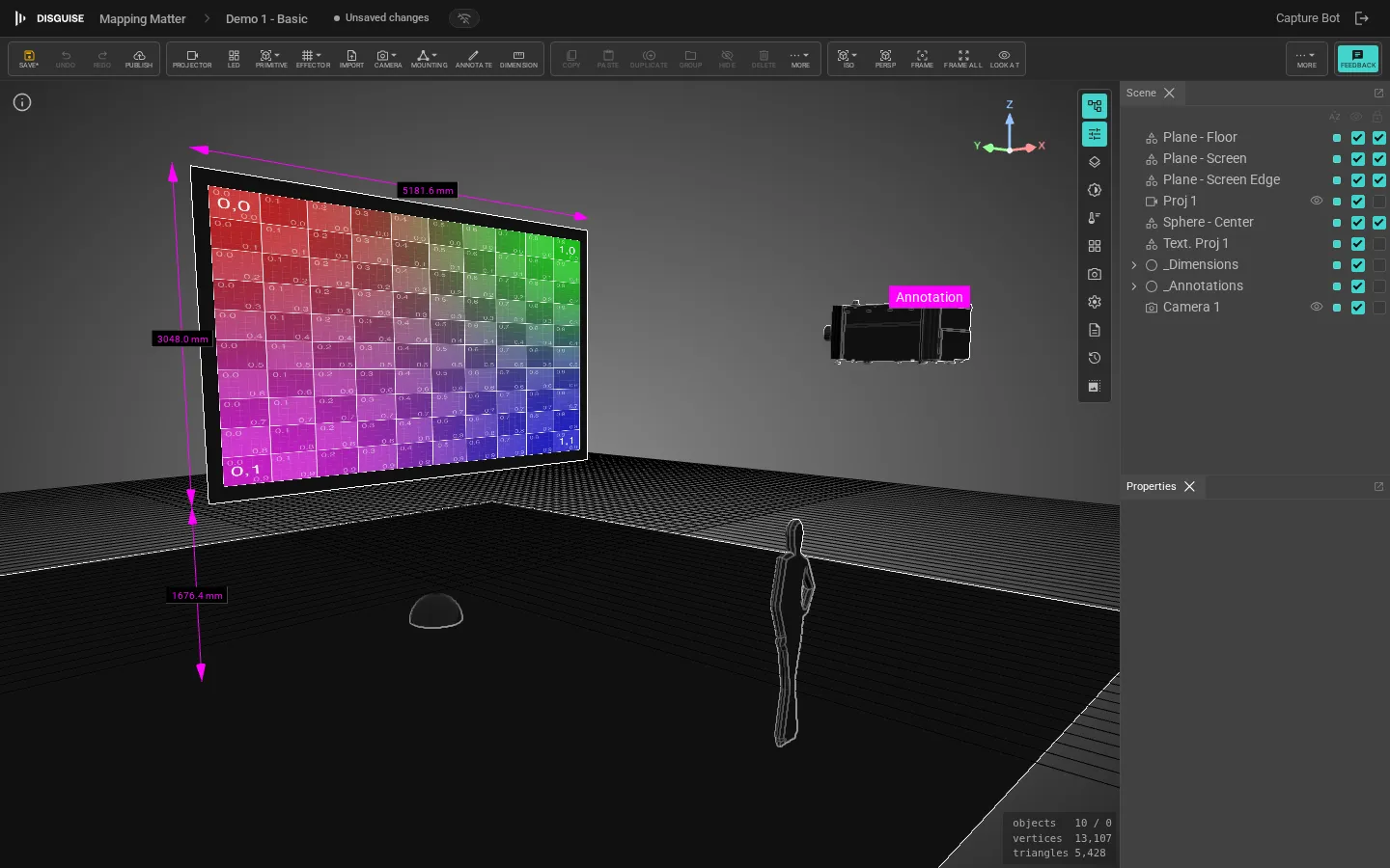
Editor layout
Section titled “Editor layout”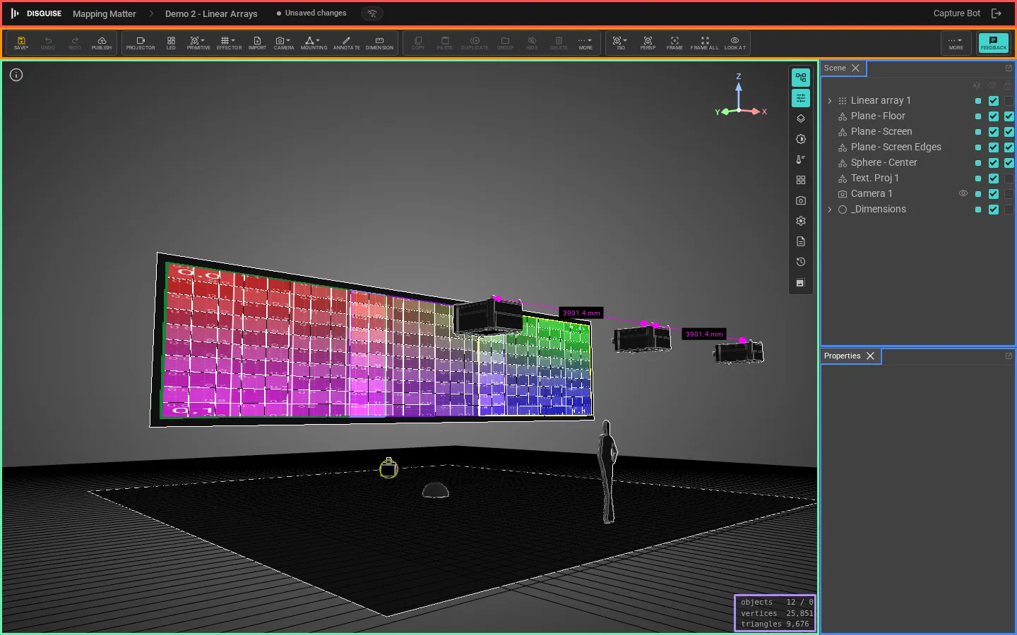
| Region | Purpose |
|---|---|
| 🟥 Header (top) | Disguise Cloud breadcrumb, scene name, network status, account menu. |
| 🟧 Viewport toolbar (below the header) | Clustered buttons grouped left to right: file (Save / Undo / Redo / Publish), add objects, edit selection, view presets, display toggles, transform space, Export, Help. Feedback is pinned to the far right. |
| 🟩 Viewport (centre) | The 3D scene. Pan with left-click drag on empty space, zoom with middle-click drag or scroll wheel, orbit with right-click drag. |
| 🟦 Scene tree and Properties panels (right) | The Scene panel lists the scene graph; the Properties panel shows fields for the current selection. Both are dockable: open or close them from the bottom-edge Panels strip. |
| 🟫 Panels strip (bottom edge) | Icon buttons for every dockable panel (Scene, Properties, Layers, Brightness, Pixel density, Camera settings, Viewport settings, PDF layouts, Revisions, Scene settings). Click any to open or close that panel. |
| 🟪 Viewport info (bottom right) | Object / vertex / triangle counts. |
If Mapping Matter deploys a new build while you’re mid-session, a Reload banner appears in the top-right corner. It’s non-blocking; click it when you’re at a good stopping point. It never reloads on its own, so unsaved work stays safe. Focus a green number field in the Properties panel and the mouse wheel starts editing that field instead of scrolling the panel; focus off, and the panel scrolls again.
The toolbar adapts to viewport width. Below 1440 px the clusters collapse to icon-only buttons, and anything still wider than the editor pulls into a right-anchored More ▾ dropdown so the ribbon never overflows.
Panels
Section titled “Panels”Click any icon button in the bottom-edge Panels strip to open or close that panel:
- Scene: scene graph tree with visibility and lock toggles per row.
- Properties: context-switched panel for the current selection (projector lens, LED tile count, material, etc.).
- Layers: bulk layer visibility and locking.
- Brightness: lux heatmap controls (see Viewport & analysis).
- Accuracy, Camera settings, Viewport settings: viewport tuning.
- PDF layouts: page templates (see Export & PDF layouts).
- Revisions: scene revision history.
- Scene settings: units, title block, auto-save.
Objects in the Scene panel are grouped into layers. Toggle a layer to hide everything beneath it, or include only specific layers when publishing a snapshot.
Reparenting in the Scene panel
Section titled “Reparenting in the Scene panel”Drag a row in the Scene panel onto another row to reparent it:
- Drop onto a node to set that node as the new parent.
- Drop above or below a sibling to reparent under the sibling’s parent in that position.
- Drag a multi-selection to move the whole top-level selection at once.
The same restrictions as the Properties Parent dropdown apply: you can’t reparent into a Reference, Pov, Measure or Annotation, into a locked subtree, or into the dragged object’s own descendants.
Rearranging panels
Section titled “Rearranging panels”Every panel is dockable. Grab the panel’s header tab and drag it to:
- An edge of the editor: the panel snaps to a new vertical or horizontal rail.
- An existing panel’s tab strip: the dragged panel becomes a tab alongside the target.
- The viewport area: the panel floats free as a movable window.
Your layout persists per scene, so the workspace you set up for a projector-heavy rig is different from the one for an LED-only scene.
Navigate the viewport
Section titled “Navigate the viewport”| Action | Mouse |
|---|---|
| Pan | Left-click drag on empty space |
| Zoom | Middle-click drag, or scroll wheel |
| Orbit | Right-click drag |
| Frame selection | F (or the Frame button in the toolbar’s view cluster) |
| Frame all | Home, or the Frame all button in the toolbar’s view cluster. With nothing framable, Home recentres the camera on its default pose so pan/zoom speed feels normal again. |
| Look at selection | The Look at button (rotates the camera toward the current selection) |
All keyboard shortcuts are listed in the Keyboard shortcuts page; press F1 at any time to open the in-app reference.
If you prefer Blender / Maya’s mouse convention, open Scene settings and turn on Swap orbit / pan mouse buttons. Left-drag then orbits, right-drag pans. Middle-click zoom is unchanged. The preference is per-browser and takes effect immediately across every open scene.
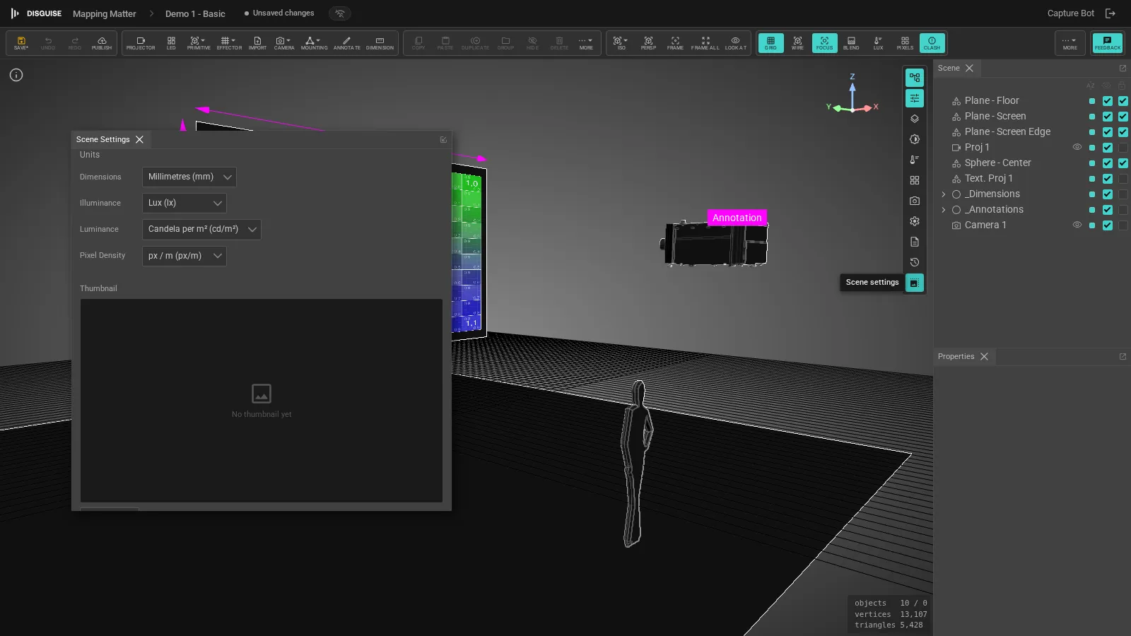
Scene units and settings
Section titled “Scene units and settings”Click Scene settings in the bottom Panels strip to open the Scene Settings dialog. Set the working unit (mm, cm, m, ft, in), background colour and gradient, fog, and the title block that travels with every published snapshot.
Add objects
Section titled “Add objects”The viewport toolbar’s add buttons are direct, with no “Add” submenu. Each button is in the second cluster from the left:
- Projector: opens the projector library.
- LED: opens the LED library.
- Primitive: popover with Plane, Box, Room, Circle, Cylinder, Sphere, Icosahedron, Torus, Torus Knot, Equirectangular Dome, Dome Master, and Empty Node.
- Effector: popover with Symmetry, Linear Array, Polar Array, and Fan effectors that duplicate or distribute the current selection.
- Import: opens the asset browser to bring in an
.obj,.fbx,.dae,.stlor.gltfmesh. Imported meshes up to 100 MB are saved to your project library; larger meshes can still be loaded locally for the current session. - Camera: popover with POV camera and Observer.
- Mounting: popover with truss types (Tower, Horizontal Span, Goal Post, A-Frame, Ladder, Arc, Ring), bases (Base Plate, GB Block, Sled, Outrigger), and a Truss library… entry for the full catalogue. See Trusses & mounting.
- Annotate (
A): start the freehand annotation tool. - Dimension (
T): start the dimension measure tool.
To add a mirror to a projector, select the projector and open the Mirror collapsible in its Properties panel; see Mirror.
Move, rotate, scale
Section titled “Move, rotate, scale”Select any object and use the transform gizmo. Numerical position, rotation and scale are available in the Properties panel for the selection. The World / Local toggle in the toolbar switches the gizmo space. Changes auto-save and are added to the revision history.
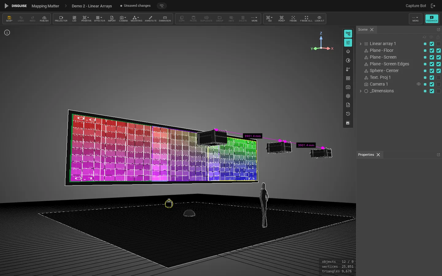
Effectors: arrays and symmetries
Section titled “Effectors: arrays and symmetries”Use the toolbar Effector button to wrap the current selection in an effector. Four modes are available (Symmetry, Linear Array, Polar Array, Fan), each with its own parameters and behaviour. See Effectors for the full reference and per-mode animations.
Materials and textures
Section titled “Materials and textures”Select any mesh and open its Material panel to set base map, projection map, colour, metallic, roughness, and emissive. Textures come from the Library; the same texture can be reused across multiple objects.
Saving, revisions and snapshots
Section titled “Saving, revisions and snapshots”You don’t need to save manually; Mapping Matter auto-saves as you work. To return to an earlier state, click Revisions in the bottom Panels strip.
- Revisions are the per-edit history of your current scene. Restoring a revision overwrites the current scene.
- Snapshots are named, locked publishes of the scene at a point in time. Snapshots are how you share the design; see Publish & share.
See Snapshots & revisions for the full model.
What’s next
Section titled “What’s next”- Add projectors and aim them: see Projectors.
- Add an LED wall: see LED screens.
- Run a photometric or brightness check: see Viewport & analysis.
- Publish your work for a client: see Publish & share.