Example 2 - OLite column
This case study shows how to prepare a column shaped LED screen constructed from Barco OLites for for Designer. As explained on the MiSTRIP Star page, the first step is to UV map the 3D model by unwrapping the mesh into a grid.
How the UV map is generated
Section titled “How the UV map is generated”A plane can be arrayed across a spline to recreate the surface with the UV map automatically generated. However, the UV map will have overlapping UV shells and therefore will require editing, either manually using UV editing tools or automatically using a script, depending on the level of complexity.
Step 1 - Generating the UV map (3ds Max)
Section titled “Step 1 - Generating the UV map (3ds Max)”- Draw a plane that matches an OLite’s dimensions, 0.084x0.112 metres.
- Ensure you have the box called generate mapping coordinates checked. Doing so will enable the plane to automatically generate a normalised UV map.
- Draw a spline that snaps to the outer edge of one OLite column.
- With the plane selected, select the Spacing tool.
- From the spacing tool’s parameters select pick path, and select the spline.
- From the spacing tool’s parameters select count, and enter a value of 34. This will array thirty four planes across the spline.
- Attach all the plane’s together into one Editable Mesh / Editable Poly.
- Clone the column by a count of 11.
- Align each column into position using the move and rotate tools.
- Attach all the column’s together into one Editable Mesh / Editable Poly.
- Select the Unwrap UVWmodifier.
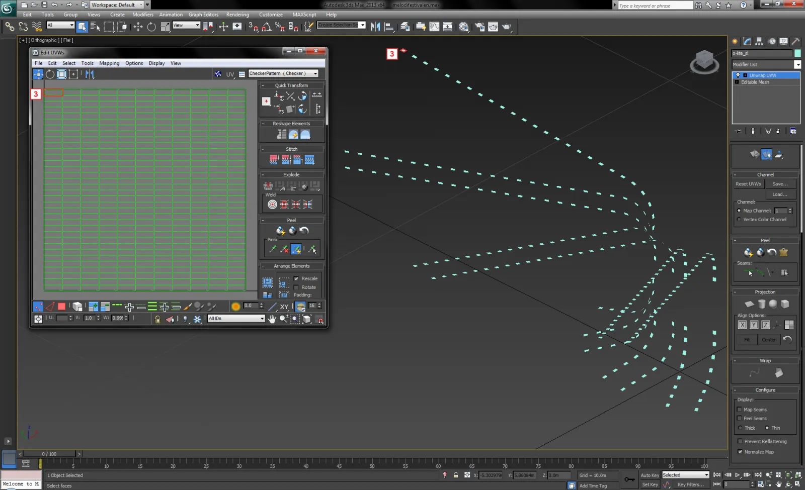
- Open the Edit UVWs window to view the UV map.
- At this stage, the UV map will have overlapping UV shells.To unwrapthe UV map, reposition the UV shells next to each other, either manually using UV editing tools or automatically using a script.
- It is important to snap the UV shells next to each other into a grid. Doing so will remove gaps in the UV map, which in turn will remove virtual pixels from Disguise’s output to the LED processor.
- Normalise the UV map by rescaling it to fill UV space entirely from a range of 0-1 in both the U and V axes.
The image below shows the OLites arrayed in a curved direction, but in UV space they are arrayed in a linear direction as a grid Importantly, the surface’s outer ring of polys correspond to the UV map’s top row of UV shells, highlighted in red. This indicates the surface’s UV shells are uniformly positioned.
Step 2 - Mapping content to screens
Section titled “Step 2 - Mapping content to screens”The image below shows a content template Feed mapped to the screen in Disguise, which was exported as an .obj file from Autodesk 3ds Max. The template was rendered from the UV map, and therefore contains no information about the physical gaps between the OLites. If video content is to be mapped to the screen with the physical gaps included, then a Feed map could be generated in d3. The Feed map samples different areas of the template, and in turn the sampled areas are mapped to the OLites. The advantage here is the sampled areas can be reconfigured, allowing for content to be moved, cropped, scaled and rotated, in the same way the Output Feeds can be reconfigured.
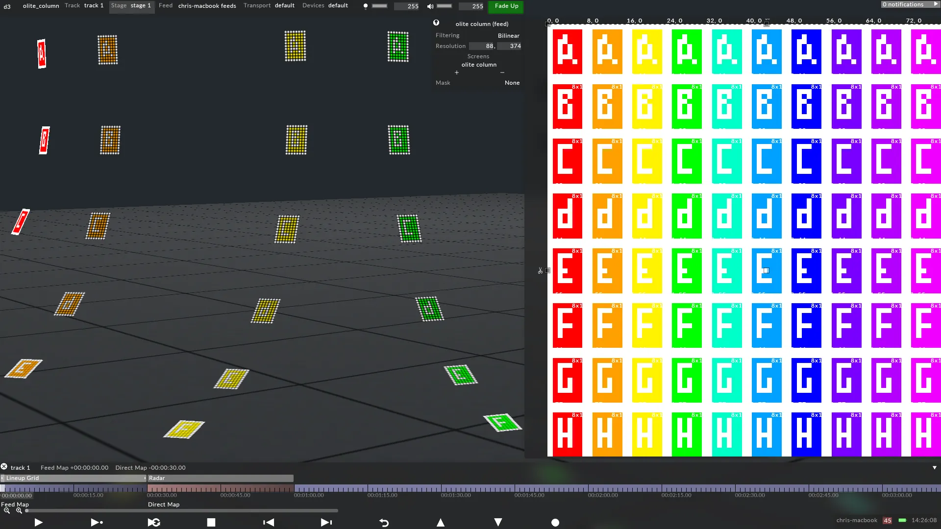
A Parallel or Perspective map can be generated from Designer. As explained on the MiSTRIP Star page, these mappingsdo not apply content directly to the screen’s UV coordinates; enabling the content creator to design content using templates that are independent of the LED outputs. Therefore, the creative workflow for the content creator is separated from the technical workflow for the hardware technicians, as explained on The UV Map as the Hardware Output page.
The resolution of the screen in Designer should exactly match the physical screen’s number of pixels. The resolution of 80x374 pixels was calculated by:
- Knowing precisely how many pixels each OLite contains horizontally.
- Multiplying this value by the total number of horizontal OLites, to calculate a horizontal resolution.
- Knowing precisely how many pixels each OLite contains vertically.
- Multiplying this value by the total number of vertical OLites, to calculate a vertical resolution.
In this case:
- 1 OLite = 8 pixels horizontally.
- The total number of horizontal OLites is 11. Therefore, 8 pixels x 11 OLites = 88 pixels horizontally in total.
- 1 OLite = 11 pixels vertically.
- The total number of vertical OLites is 34. Therefore, 11 pixels x 34 OLites = 374 pixels horizontally in total.