TestPattern Layer
The TestPattern layer renders a calibration pattern made up of a configurable grid, concentric circles, the screen’s label with its resolution, and corner logos. The pattern helps verify screen output, alignment, mapping, and resolution during setup, before content goes live.
Workflow
Section titled “Workflow”-
Create a new layer
-
Assign the layer to a mapping
- Define the circles, grid, and other parameters to suit
TestPattern Layer Properties
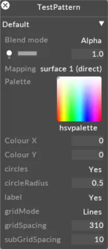
Section titled “TestPattern Layer Properties”Circles
Section titled “Circles”Defines whether the test pattern displays circles. Default: yes.
Circle radius
Section titled “Circle radius”Defines the radius of the circles. Range: 0-1 (step 0.0125). Default: 0.5.
Defines whether the screen or projector label is shown in the centre of the pattern. The label is followed by the screen’s resolution (e.g. 1920 x 1080). Default: yes.
Grid mode
Section titled “Grid mode”Selects the grid style: Off or Lines. Default: Lines.
Grid spacing
Section titled “Grid spacing”Spacing between major grid lines, in pixels. Range: 1-1000. Default: 100.
Sub grid spacing
Section titled “Sub grid spacing”Spacing between minor grid lines (subdivisions within each major grid square), in pixels. Range: 1-1000. Default: 10.
Logo top left
Section titled “Logo top left”Texture slot for the logo rendered in the top-left of the pattern. Defaults to the Disguise logo.
Logo bottom right
Section titled “Logo bottom right”Texture slot for the logo rendered in the bottom-right of the pattern. Defaults to the Disguise logo.
Input Exposure
Section titled “Input Exposure”Input exposure transform applied to the test pattern, in stops. The available range depends on the active colour management mode — ACES: -5 to 5 (step 0.1); OCIO: -10 to 10 (step 0.1).
Input Contrast
Section titled “Input Contrast”Input contrast transform. Range: 0-5 (step 0.01). OCIO mode only.
Input Gamma
Section titled “Input Gamma”Input gamma transform. Range: 0-5.
Common Layer Properties
Section titled “Common Layer Properties”Brightness
Section titled “Brightness”This property (which appears as a light bulb icon) controls the brightness of the layer output.
If the layers blend mode is set to Alpha, then reducing the brightness to 0 also reduces the opacity of the layer to 0. This can be useful when you want to dissolve from one layer to the next. In that case, you can place the new layer above the old layer and increase its brightness level.
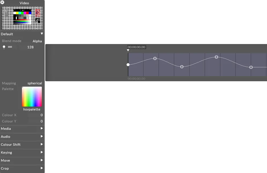
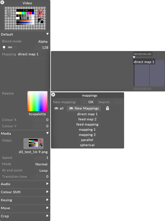
Mapping
Section titled “Mapping”The mapping property controls how the layer output is mapped onto the screen(s) in the Stage level.
For information on mapping, including how to use the different mapping types offered by Designer, please see the chapter Content Mapping
Palette
Section titled “Palette”This points to the still image file that defines the bitmap from which the tint colour is taken. The default palette ( HSVPAL ) consists of the complete range of hues and saturations. Selecting this property will open the Texture object library, which shows all of the still image files saved on your local hard-drive in the DxTexture older.
To control the location within the current palette bitmap, and thus control the colour, you have to edit the xCol and yCol values (see the section for xCol, yCol).

To change the current palette bitmap:
- Left-click palette to open the Texture object library.
- Left-click the still image file you want to use for the palette bitmap.
If you want to use a palette bitmap other than the standard still images provided in Designer, you will need to use a custom still image file.
See the Placing media files for a project sub-chapter to understand where to place a custom still image file and how to access it in Designer. Also save the file to a supported file format.
Xcol, YCol
Section titled “Xcol, YCol”These properties control the coordinates within the current palette bitmap where the output colour is sampled from. The default value is 0,0 which points at the color white (if you are using the HSVPAL palette). Multiplying white with the colors of the chosen content simply generates the original content colors. Colour X controls the horizontal position, where 0 is the leftmost edge and 255 is the rightmost edge. Colour Y controls the vertical position, where 0 is the top edge and 255 is the bottom edge.
For example, to saturate the video clip red, change the Colour Y value to 255 and use 0 for the Colour X value. These coordinates refer to the color red in the palette which is being multiplied with the colors of the existing content.
When you are using the default palette HSVPAL , Colour Y controls saturation, and Colour X controls hue.
