OmniCal Alignment
Alignment is a user-guided process that is required to align the calibrated data with the coordinate system in Designer. OmniCal also includes the ReShape feature to adjust 3D model vertices based on the user alignment.
OmniCal Stage Plan
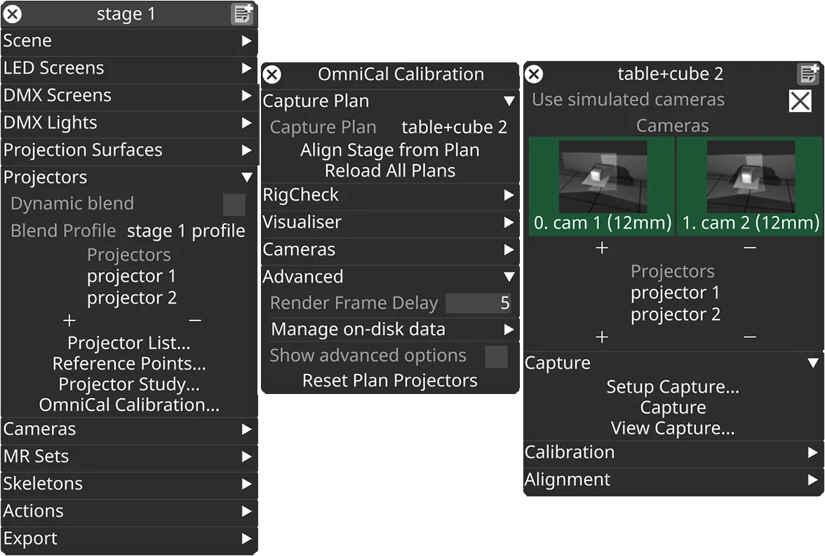
In the Stage editor, under Projectors, click OmniCal Calibration to open the Calibration editor. This widget controls the main OmniCal behaviour. Right-click on any Capture Plan to open its OmniCalStagePlan editor.
In the OmniCalStagePlan we recommend working through the sections from top to bottom: Capture, Calibration, Alignment, and Mesh Deform (if required).
Alignment
Section titled “Alignment”Alignment is the process of registering or aligning the coordinate system of the captured point cloud with that of Designer. It is a required step to make the projector output match the physical scene after OmniCal calibration has finished. A good alignment is a requisite for further steps like Mesh Deform.
Perform Alignment
Section titled “Perform Alignment”-
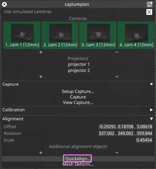
In the plan editor, roughly edit the point cloud Alignment via Position, Rotation and Scale. This does not need to be exact at all, just close enough in terms of scale and rotation that further steps are made easier.
-
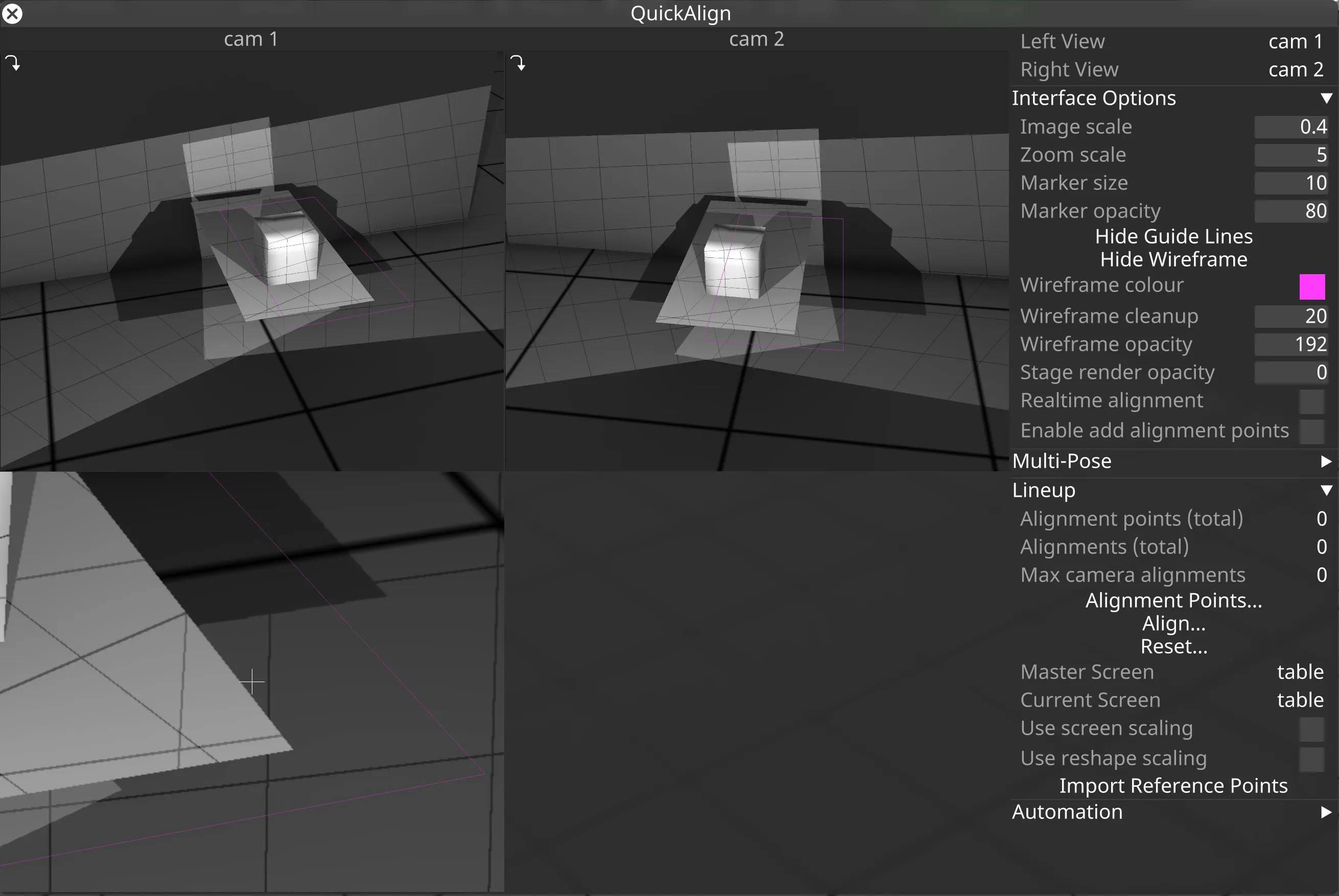
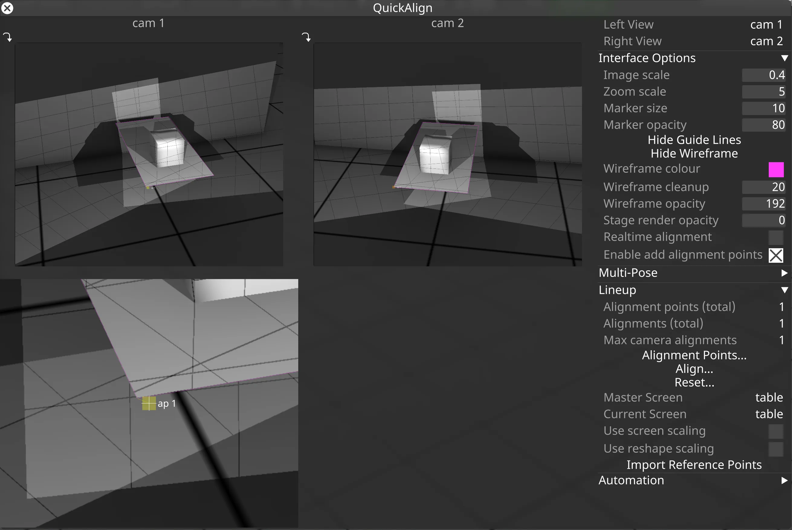
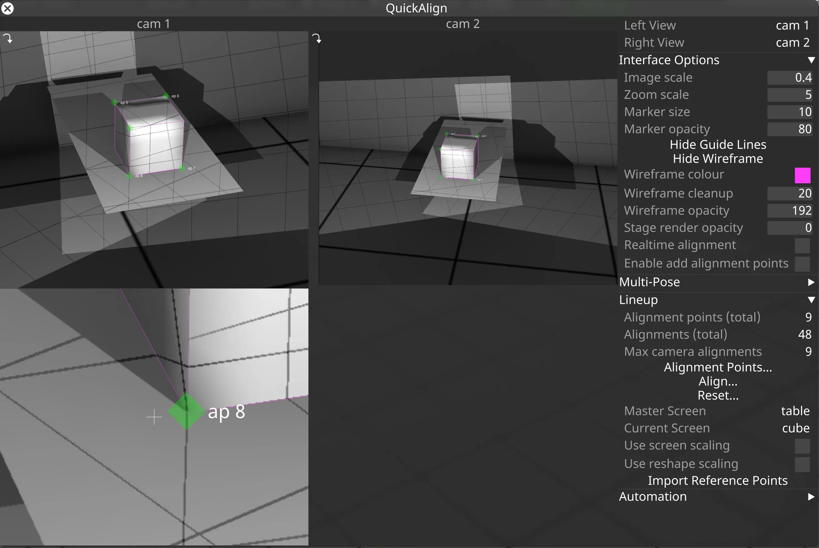
Once the point cloud is roughly aligned (i.e. somewhat close to the projection surfaces in the visualiser), click QuickAlign… to open the tool for detailed alignment. In QuickAlign you should see a reprojected wireframe of the first projection surface, drawn on top of the alignment image taken for each camera.
- The top two views relate to the cameras currently selected as Left View and Right View in the top right corner.
- If the cursor is located in one of the camera views, then a zoomed-in view will be shown below it. This is essentially a magnifying glass for precise alignment of vertices to pixels in the camera image.
- The Interface Options allow adjustments of QuickAlign UI elements to improve visibility during the alignment process. Most importantly, the alignment point marker size, opacity and the wireframe opacity and colour can be adjusted.
-
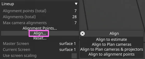
There are tools to automatically align the point cloud to the stage. In QuickAlign click Align… to open a menu with alignment methods:
- Align to estimate creates an initial alignment estimate based on point cloud coordinates and vertices of all projection surfaces. This is not accurate, and requires that there is a good overlap between point cloud and all meshes, with little to no missing or extra areas.
- Align to Plan cameras uses the positions of plan cameras. Requires that the planned positions of plan cameras are somewhat realistic.
- Align to Plan cameras & projectors uses the positions of plan cameras and projectors. Requires that the planned positions of plan cameras and projectors are somewhat realistic.
- Align to alignment points uses the manually created alignment points in each camera. Use this option when you want to (re-)apply the current
alignment point data (see below) to the stage.
-
In most real-world environments the automatic Alignment tools don’t provide a good enough alignment. To manually improve the alignment, create AlignmentPoints and line them up in multiple cameras. At least 3 alignment points need to be lined up in at least 2 cameras each. It’s best to edit the alignment points one by one in each camera view. Alignment points are best placed on mesh vertices that correspond to distinct features in the physical model (e.g. a corner of a building). Not every camera will see every alignment point, so additional points may be needed.
-
Create AlignmentPoints:
- Enable the checkbox Enable add alignment points.
- Click near a vertex on the wireframe to create an AlignmentPoint for this mesh vertex.
- Alternatively, AlignmentPoints can be imported from existing QuickCal projector ReferencePoints.
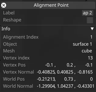
- Right-click on a point to access and edit its properties.
-
Drag the AlignmentPoint to the corresponding area in the camera image. Do the same for the corresponding point in the second camera view.
-
Repeat this process for a minimum of three points.
- The currently selected AlignmentPoint will flash its marker. While it is selected, it can be moved using the arrow keys on the keyboard.
- Hold SHIFT + arrow keys to move the AlignmentPoint marker faster.
- Hold CTRL + mouse movement for slower fine control movement.
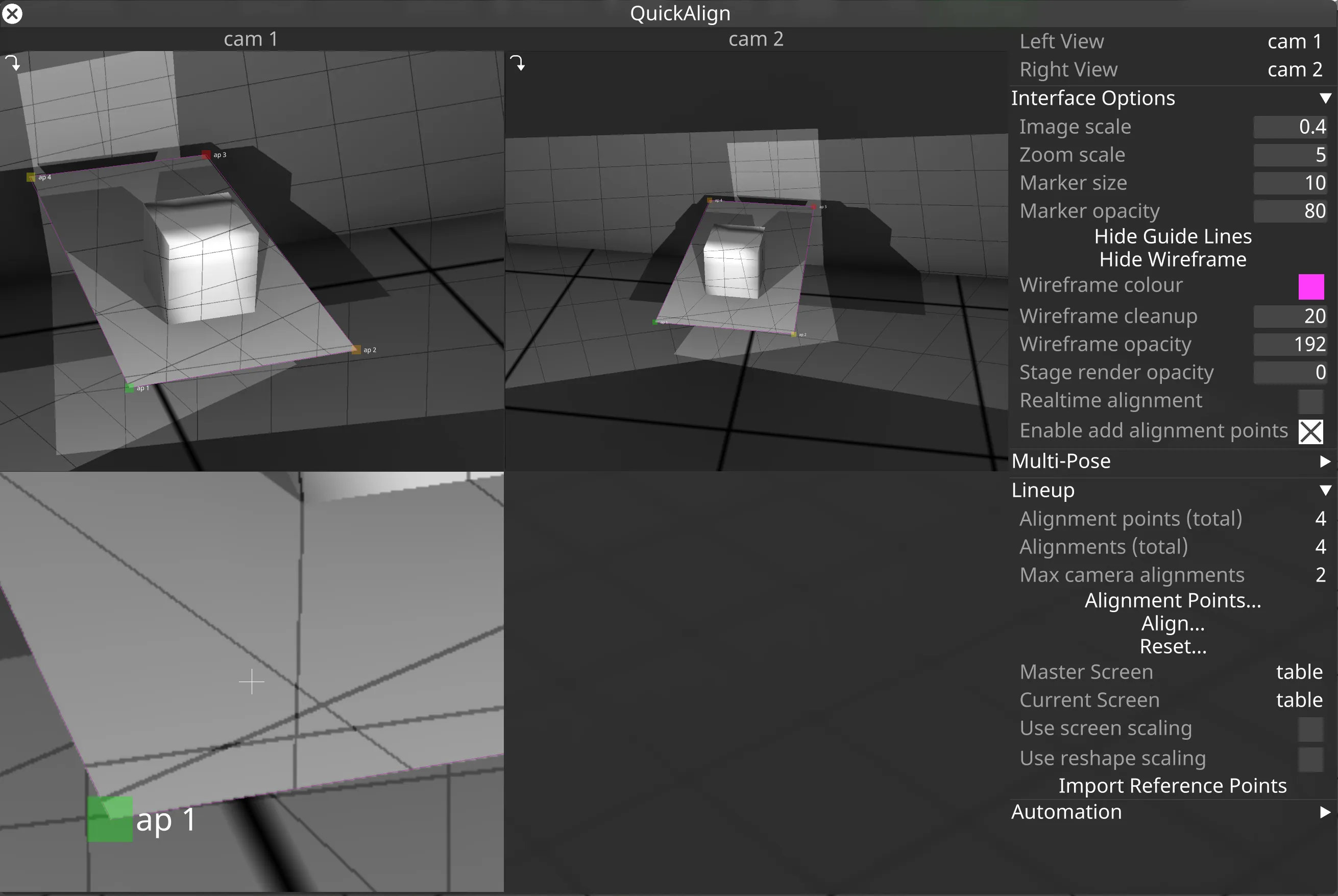
AlignmentPoint markers are drawn in different colours, based on their alignment state:
- Red: This point is not being used as part of the alignment, but has been added to the view.
- Yellow: It has been aligned only in the current camera. It is not used in the alignment calculation until it gets aligned in another camera.
- Orange: It has been aligned only in a different camera.
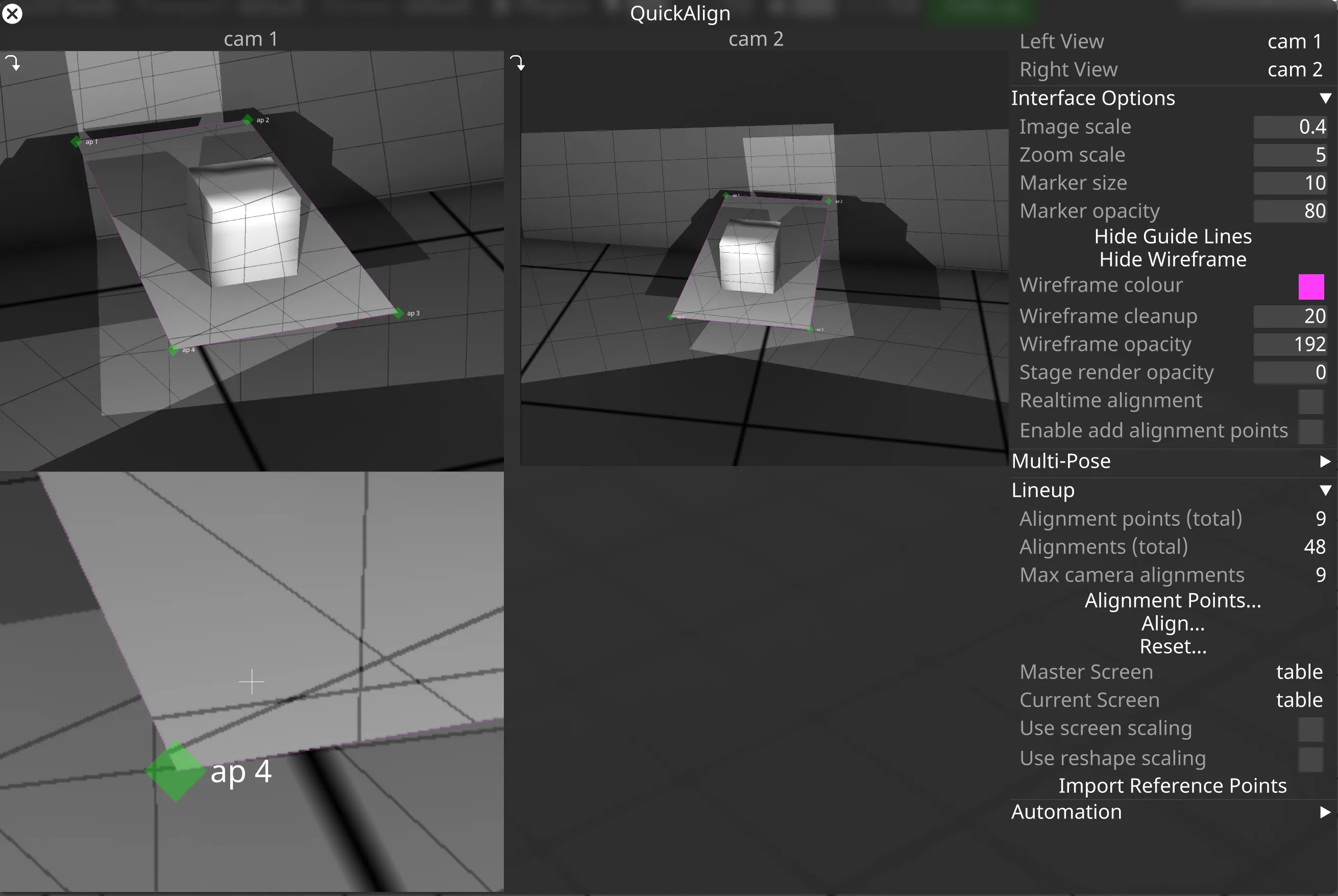
- Green: It has been aligned in at least two cameras, and therefore is used in the alignment calculation.
Multi-screen Alignment
Section titled “Multi-screen Alignment”If there is more than one screen in the plan, it may be helpful to use Multi-screen alignment. This allows aligning surfaces in the stage based on the captured images and a common master screen. If the relative offset and rotation between all surfaces in the stage matches the relationships of the actual physical surfaces, then this may not be needed.
- The master screen should be aligned first.
- The master screen acts as a registration base for all other screens. Reshaping or scaling of the master screen will therefore affect all other screens.
- When aligning secondary screens, they will be moved to the correct position relative the Master screen.
- When stage automation is used to control physical screen positions, it is best to choose a non-moving surface as the master screen.
An example for how to align multiple surfaces can be seen in the demo video from the Overview page, at around 2:40 minutes.
Alignment Reshape
Section titled “Alignment Reshape”If the proportions of the model match the physical surface exactly, then the alignment should fit perfectly. But if the proportions are not correct, you may need to perform Alignment reshape. Reshape allows adjustments to mesh vertices based on lined-up alignment points. This can be useful for adjustments such as stretching or squeezing the projection surface, or even moving some internal mesh elements (such as a window) by a certain amount. Typical applications are in theatre where scene elements are built according to a CAD drawing, but the physical construct ends up with minor deviations due to the construction process or limitations imposed by the stage.
The reshape process does not use the captured point cloud, but simply adjusts existing mesh vertices and mesh proportions. This is done according to the calibrated cameras, captured alignment images and alignment point data provided by the user. UV coordinates for a vertex are not modified during Reshape.
Enable Reshape
Section titled “Enable Reshape”- To enable Reshape for an alignment point hold SHIFT and left-click it. This will turn it into a reshape point which is indicated by a diamond marker (45 degree rotated).
- Left-click the point again (without holding SHIFT) to turn it back to a non-reshaped alignment point.
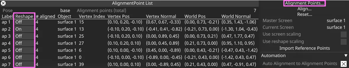
Alternatively, right-click an AlignmentPoint to open its editor, and toggle the Reshape checkbox.
The AlignmentPoint List widget offers a quick way to toggle Reshape for all alignment points.
An example for how to use reshape points can be seen in the demo video from the Overview page, at around 4:24 minutes.