Parallel Mapping
Parallel mapping projects content geometrically into the scene, as if virtually shooting content from an emitting rectangle. The mapped image does not increase in size the further away you go from the emitting rectangle. Instead, the image remains the same size, hence the term parallel.
Parallel mapping will emit content over multiple screens and treat the configuration as a single canvas, projecting one unified image over all assigned surfaces. There is no more need to calculate the exact distance and pixel density of the empty space between screens, Designer will maintain the correct content sampling even across moving surfaces.

Parallel mapping is also very useful when you want to apply content onto moving screens. As long as Designer receives the correct tracking signal, the system will automatically map the content onto the moving screens. See more about screen tracking in the sub-chapter Motion control systems.
Parallel mapping is a versatile method for integrating multiple display technologies—including LED systems with varying pixel pitches, projection, and DMX-based lighting—into a unified canvas. Since Disguise represents all outputs as pixel-based surfaces, whether LED, projection, or DMX fixtures such as moving heads, it enables precise spatial alignment and seamless blending of these diverse display types within a single coordinate space.

Creating a Parallel Mapping
Section titled “Creating a Parallel Mapping”- In your track, create a new visual layer. These layer types can include content layers, generative layers, and effect layers.
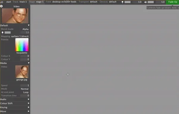
- Left-click on the layer in the track to open the Layer Editor on the left side of the GUI.
- Under the Default tab, left-click on the Mapping parameter to display a list of the mappings in the project.
- A manager titled mappings will appear - this is a list of all mappings within your project. By default, all screens will be populated with a direct mapping sharing the same name, and all cameras will be populated with a perspective mapping sharing the same name.
- Type directly into the ‘New mapping:’ text field to create a new mapping. A list will appear prompting to you select the mapping type.
- An editor with the user assigned name of the mapping will appear once a mapping type is selected.
- Assign all screens that will be used for the mapping and enter the resolution of the content that will be displayed on the screens.
- Edit the specific properties of the chosen mapping type.
- Assign a piece of content to the layer in the track, and the content will be displayed on the assigned screens of the mapping in the stage and the feed output window.
When the Parallel mapping editor initially opens, and assuming that the screens have been added, Designer will colour the region outside the projected image red and will give you the location and orientation details of the image source.ce.
Common Mapping Properties
Section titled “Common Mapping Properties”This section explains the properties that are shared by the different mapping types.s.
Filtering
Section titled “Filtering”-
Nearest: Nearest neighbour filtering. Use nearest-neighbour sampling, to disable blending between pixels when scaling. Can be used to create pixellated looks, or to ensure hard edges on certain types of content.
-
Bilinear: Bilinear filtering is a texture filtering method used to smooth textures when displayed larger or smaller than they actually are.
-
2x Multi-sample: Multi-Sample filtering can help fix issues with scaled content, but can introduce some blurriness.
Resolution
Section titled “Resolution”This controls the canvas size the layer renders into, in pixels. The Direct mapping type starts with a 256x256 pixel canvas and automatically sets the canvas size to that of the first screen you add.
Screens
Section titled “Screens”This is a list of screens that the selected mapping type can copy content to.
- Left-click + to open the Screens manager.
- Left-click + to add the Screens you want to map. This will copy the individual canvas content onto these three Screens simultaneously and will add the Screen names to the mapping object editor.
- Left-click and drag the Screens listed in the mapping object editor to -. This will remove the canvas content from the Screens and delete the Screen names from the mapping object editor.
This points to the Texture file that defines a Mask bitmap. You can use this property to apply a Mask bitmap to the mapping canvas. Selecting this property will open the Texture object library, which shows all of the still image files saved on your local hard-drive in the DxTexture folder.
To apply a mapping mask you will need to create and import a custom still image file.
-
The step-by-step instructions on how to create and import a custom Population mask can be used to create a custom mapping mask. The only difference is that the mapping masks resolution should be the same as the mapping canvas. For step-by-step instructions on how to create and import a Population mask into a d3 project visit to the section Population mask in the Editing screens sub-chapter.
-
Alternatively, set any layers blend mode to mask to channel the layer content into the mapping mask.
Clip outside region
Section titled “Clip outside region”Clips pixels outside of rendered region, preserving existing colour. If not set, pixels outside the rendered region are set to the border colour.
Border Expansion
Section titled “Border Expansion”UV islands on screens are expanded by this many pixels to cover edge sampling artifacts such as black fringing. Note that there must be an equivalent amount of empty space in the screen UV map to take advantage of this.
Find/Replace Usages
Section titled “Find/Replace Usages”Finds all usages of the current mapping in the project, and allows these to be replaced with an alternative mapping. Note that replacement only works for sequenced, non-sockpuppeted mappings.
Hierarchy
Section titled “Hierarchy”The hierarchy section allows the mapping to be set as a parent or child of another object, like any other object. See Object Overview for details.
Parallel Mapping Properties
Section titled “Parallel Mapping Properties”For convenience while editing, the mapping can either maintain its aspect ratio, which changes vertical size or resolution when you change horizontal size or resolution, and vice versa. The pixel density, which changes the vertical or horizontal size when you change the vertical or horizontal resolution can also be locked.
Anchor
Section titled “Anchor”This controls the anchor point around which the mapping surface moves, scales and rotates. Select either centre to specify the position of the centre of the projection image or select corner to specify the bottom left corner of the image.
This controls the size of the mapped image, in meters (horizontal and vertical).
Angle mask start (°)
Section titled “Angle mask start (°)”This sets the starting point of the visible texture projection, measured in degrees around the axis. For example, a start angle of 0 degrees would typically be the “front” or a predefined reference direction.
Angle mask end (°)
Section titled “Angle mask end (°)”This sets the ending point of the visible texture projection. The texture will only be visible between the start and end angles.
Position
Section titled “Position”The position, in stage space (in metres) of the anchor point of the mapping source. This can be either the centre of the image or the bottom left corner of the image.
Heading
Section titled “Heading”This controls the direction of the mapping in the horizontal space, in degrees. Increasing the angles will make the direction to rotate clockwise.
- 0 degrees points North (positive z axis direction)
- 90 degrees points West (negative x direction)
- 180 degrees points South (negative z direction)
- 270 degrees points East (positive x direction)
Elevation
Section titled “Elevation”This controls the vertical elevation, in degrees, of the projection direction: 0 degrees is horizontal (i.e. parallel to the floor), 90 degrees is straight up and 90 degrees is straight down.
Rotation
Section titled “Rotation”This controls the rotation of the image around the mapping axis, clockwise in degrees.
Content mode
Section titled “Content mode”This defines the mode of content, either 2D or 3D.
Frame of reference
Section titled “Frame of reference”This setting dictates how the projected texture behaves when your object or the camera moves.
This is set to None by default.
Using the Parallel mapping type
Section titled “Using the Parallel mapping type”In addition to the property explanations provided above, it is important to:
- Set the aspect property to off and set the resolution to match the resolution of the content intended to be used for this specific Parallel mapping.
- Set the size of the emitting rectangle of the Parallel mapping to match the aspect of the resolution (and thereby the aspect of the content) and then set the aspect to locked . For example, if your content is 1920x1080, set the size to 19.2 10.8 and then set the aspect to lock . If the aspect or the density of the source content is not locked the Parallel mapping may project stretched pixels onto the screens.
- Re-size the x or y coordinates to cover all areas of the screens (the red areas will gradually disappear as you re-size the emitting rectangle).
- Make sure to specify content which has the same, or a slightly higher pixel density than the screen with the highest pixel density.