Visca Camera Device
A VISCA camera is a professional video camera that uses the VISCA protocol (Video System Control Architecture), to allow external devices to remotely control its functions. This protocol is used to adjust settings like zoom, focus, and white balance, and is common in pan-tilt-zoom (PTZ) cameras used in broadcasts, video conferencing, and live streaming. The control can be sent over serial connections or, more commonly now, over an IP network.
Disguise supports controls sent over an IP network only.
This topic outlines the setup steps in order to control VISCA-compatible PTZ cameras over network using a Disguise media server.
Visca Camera Setup
Section titled “Visca Camera Setup”Requirements
Section titled “Requirements”-
VISCA Camera that supports IP connectivity.
-
Optional Disguise machine with a relevant capture card (only if you want to use the camera as a live video input).
Workflow
Section titled “Workflow”- Create a UDP device from Device Manager.
- Set the IP Address
- Set the Port on the UDP device
- Create a Visca Camera device from Device Manager.
- Set the Address.
- Set the Control Device to the UDP device.
- Set the Camera Model.
- Create a CameraControl layer on the timeline.
- Set the Camera field to the camera that was created earlier.
- Click the Command field to open up the keyframe editor.
- Create and keyframe your desired commands for the camera.
Creating a UDP device
Section titled “Creating a UDP device”For detailed steps on creating a UDP device, see UDP Device.
Create a ViscaCamera device
Section titled “Create a ViscaCamera device”- Right-click devices from the dashboard. This will open the Device Manager, which contains a list of active devices.
- Select + to open the Device library. This lists which internal or external devices are available.
- Type in the name of the new device into the new device text field.
- Hit Enter. This will open a list of device types available in Designer.
- Select the ViscaCamera device type. Type the name exactly — one word, capital V and C — variations such as “Visca Camera” will not match.
Controlling the camera
Section titled “Controlling the camera”- Create a CameraControl layer and add it to the timeline. For more information see Creating layers.
- Create presets and keyframe accordingly. For more information, see CameraControl layer.
Mapping the camera to a video input
Section titled “Mapping the camera to a video input”To bring the camera’s live video feed through Designer and output it to a physical screen:
- Patch the capture input to a Video Input Clip (e.g.
videoin_1) in the Video Input Patch manager. - Create a Video layer.
- Set the layer’s media property to the Video Input Clip from step 1.
Visca Camera properties
Section titled “Visca Camera properties”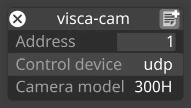
Address
Section titled “Address”The VISCA address of the camera being controlled. Multiple cameras on the same network are distinguished by address.
Control Device
Section titled “Control Device”The device in the device manager that communicates with the physical camera — typically the UDP Device created earlier.
Camera Model
Section titled “Camera Model”Select the type of camera that supports the VISCA protocol. Currently supported models: 300H and 360SHE.