Colour calibration
Disguise Colour Calibration is a process used to standardise colour representation across physical LED panels and virtual set extensions in an xR environment.
Variations in LED panel output, due to differences in manufacturer specifications, panel age, or batch inconsistencies, can result in perceptible mismatches between physical and virtual elements. The colour calibration workflow compensates for these discrepancies by generating a 3D LUT (Look-Up Table) that characterises and adjusts the LED output to align with the intended virtual colour space.
The calibration process measures the LED display’s colour response and reconciles it with the system’s reference values, ensuring consistency across all visual surfaces. This enables accurate blending of content between real and virtual components, even when using LED panels from different vendors or with different physical properties.
Workflow
Section titled “Workflow”- Complete spatial and delay calibration in full.
- Bring all lighting, LED and cameras to optimal settings and clear the stage of any physical items.
- Fill the camera frame with LED pixels.
- Open the MR set.
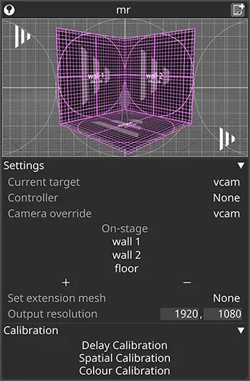
- Open the Colour calibration menu.
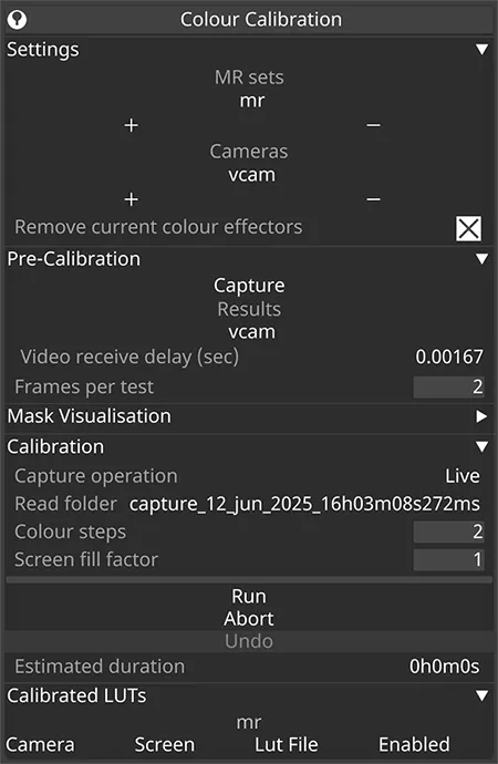
- Ensure the correct MR sets to be calibrated have been populated in the Settings tab.
- Expand the Pre-Calibration tab. The Video receive delay should be autopopulated from the Delay calibration. The camera will be automatically taken from the active camera of the MR set. For multicam setups, include all cameras to be calibrated.
- Click Capture.
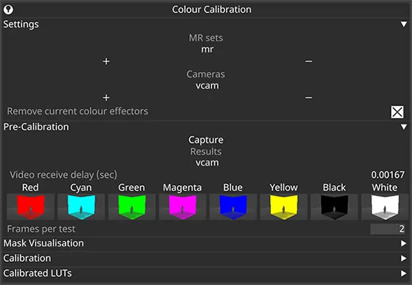
- Step up incrementally in the Frames per test field until the colours in the preview are saturated and appear to be true representations of each colour.
- This ensures that all steps of each colour range are correctly captured by the camera.
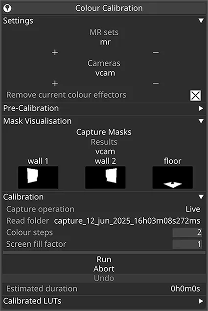
- Optionally, expand the Mask Visualisation tab.
- Hit Capture Masks to generate a preview of the calibration mask for each LED-screen/camera pair. Review that any occlusions are correctly masked in black and that the white regions cover only the screen surfaces used for calibration. To make this pre-flight check meaningful, ensure the setup remains unchanged between previewing masks and performing the actual colour calibration. – These preview masks are for inspection only; fresh masks will be generated during the actual colour calibration.
- Expand the Calibration tab.
- Hit Run to start the calibration. Ensure the camera does not move and lighting levels do not change. Once complete, a mapping will be created for each combination of camera/LED screen/LUT file as determined by the elements included in the MR set object.
- Expand the Calibrated LUTS tab to toggle on and off each LUT if needed.
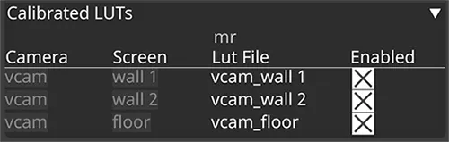
- Increase the value of the Screen Fill Factor if lighting from each LED is spilling onto the edges of the floor and affecting the calibration result. When the value is set to 1, the colour output will fill 100% of the screen.
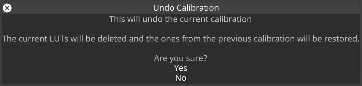
- If a previous colour calibration was in place before running the current one, it will be automatically backed up. You can restore the LUTs from the previous calibration by clicking the Undo button under the Calibration tab and selecting Yes when the confirmation prompt pops up.
Each physical camera will require its own colour calibration, the LUTs are switched automatically by the indirection controller when it switches cameras.
If the Capture operation mode is set to Write, thumbnails of each colour calibration step will be written to the debug captures folder within your project. This can be useful for sending to the support team to reproduce any issues you may encounter.
For further colour adjustment to the set extension, a Colour Adjust layer can be created and assigned a CamPlate Mapping set to backplate with all cameras used for the MR transmission added as the mapping objects.