OmniCal Multi-Pose Alignment
Multi-pose alignment is an QuickAlign tool to allow projection on moving objects that are controlled by simple automation.
OmniCal QuickAlign positions secondary (non-master) objects relative to the master object. The normal workflow already allows users to align multiple objects separately from the master object. This is useful when the relative distance and angle between objects in the real world are unknown.
A multi-object scene supports projection on moving scenery if accurate 3D tracking data is available for all moving objects. However, often objects are moved on stages using 1D automation systems that provide accurate 1D motor information instead of 3D tracking data. Multi-pose alignment exists for this use case: it allows users to create accurate 3D poses for a moving object, where each pose is linked to a certain automation axis value.
Multi-pose alignment expands the alignment of secondary objects (but not the master screen) to cover motion. It adds the ability to align an object in multiple poses (position and orientation), where each aligned pose is associated with the automation value recorded at that time. Designer can then interpolate between the aligned poses based on the current incoming automation value. The interpolation produces new 3D poses between the recorded and aligned poses. This enables correct projections onto moving objects, even though the automation system itself only provides a single-axis value.
Currently, only movement along a linear path is supported, which requires 2 poses per object. These poses are typically chosen as the two extreme poses where the object is visible.
This workflow is for Multi-Pose Alignment in OmniCal, and not to be confused with QuickCal’s Multi-Pose calibration of e.g. rotating objects.
Prerequisites
Section titled “Prerequisites”- A stationary master screen is required, in addition to any projection objects that are moving.
- Accurate Meshes: Multi-pose is designed to interpolate between object poses. These poses are determined by alignment points, therefore an accurate 3D model is required.
- For optimal calibration, the master screen should match real-world scale, as it sets the reference for the entire setup. If the master screen scale is incorrect, adjustments may be needed for all secondary screens.
Limitations
Section titled “Limitations”- Only supports linear paths, with a single input value from the automation system.
- Does not support calculating rotation pivot points.
- If an object rotates between poses, the system will simply linearly interpolate between these rotations, which may not be what is desired.
- Multi-pose alignment only uses a single calibration (it is not multi-pose calibration like QuickCal). Therefore, there are some important requirements for projector calibration:
- Projectors need to be calibrated with depth (e.g. using the DLT algorithm). Blobs cannot be on a single plane (coplanar).
- Projection will only be accurate within the calibrated “space”, i.e. around the volume enclosing the blobs. Surface movement should be limited to this area. As always, Blobs that land on the floor or areas behind the object will be helpful in extending the calibrated volume.
- No mesh interpolation is done.
- Multi-pose alignment is not supported by the Rig Check workflow.
- It shouldn’t normally be necessary to use Multi-pose on a regular basis.
- It should only be necessary to redo it when there are changes to the automation system, causing screens to move along a different path.
Workflow Overview
Section titled “Workflow Overview”- Extract high-quality meshes.
- Set up automation axes for all moving screens.
- Perform a capture and calibration.
- Align master screen and all static screens in the base pose.
- Create two poses for each moving screen.
Detailed Steps
Section titled “Detailed Steps”1. Extract high-quality meshes
Section titled “1. Extract high-quality meshes”The multi-pose workflow requires that you have accurate meshes. You can skip this step if you already have these or if you are in a simulation.
Please see Extracting a mesh using OmniCal for further information.
2. Set up automation axes for all moving screens
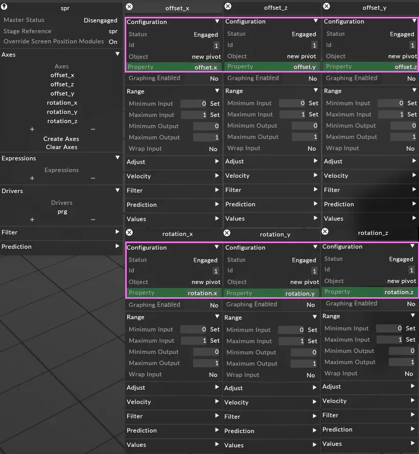
Section titled “2. Set up automation axes for all moving screens”- Create an automation device and driver using the regular workflow.
- Create 6 axes, all with the same input ID from automation, for XYZ position and XYZ rotation of the object as follows.
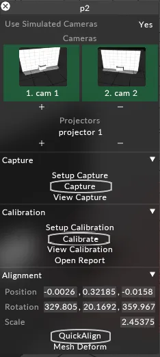
3. Perform a capture and calibration
Section titled “3. Perform a capture and calibration”4. Align the master screen and all static screens in base pose
Section titled “4. Align the master screen and all static screens in base pose”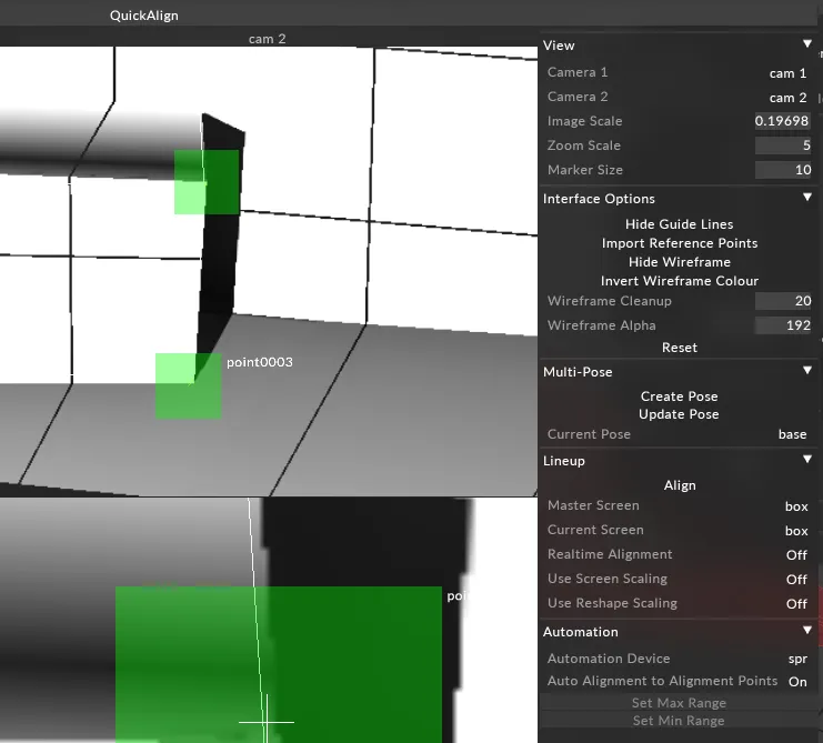
Align the Master screen
Section titled “Align the Master screen”- Make sure that the Current Pose in QuickAlign is set to base and that the Master Screen and Current Screen are set to the actual master screen object in the visualiser.
- Perform an alignment, as usual.
- Repeat for all static screens.
- You can only use reshape tools in the base pose. In other poses, the current mesh is being moved, but no further reshaping is supported.
- Note that for other poses, the UI does not yet prevent you from turning alignment points into reshape points.
- If you need to reshape a mesh for which you need to use the Multi-Pose workflow, then you can either do this by aligning and reshaping in the base pose, or doing it in a separate step, and export+re-import the mesh (probably preferred).
5. Create two poses for each moving screen
Section titled “5. Create two poses for each moving screen”In most cases, it will be enough to create two poses: a minimum and maximum pose, each for the most extreme position in which the object will be visible / projected on. For example, if a projection surface is moved from left to right, then these are the most left and most right positions in which enough alignment points are still visible to produce a reliable alignment.
When a new pose is created, a new short capture is taken by OmniCal. This capture only contains alignment images that are used within QuickAlign to help with object alignment. These captures do not contribute to the calibration result, only to multi-pose alignment.
You can right-click on a pose to view the screens and automation data contained within it.
Create min Pose
Section titled “Create min Pose”- Enable OmniCal camera discovery.
- With the Quick Align editor open, ask your automation operator to move the moving object to its minimum visible position.
- Click Create Pose.
This will take a capture and present the camera images for the user to align to. It will also take a snapshot of the current automation input values. - Select the object which has just been moved by automation as the Current Screen to be aligned.
- Perform an alignment of the screen at this minimum position.
Each pose can contain multiple screens, so you can repeat this for each screen that is visible. Alternatively, you could create a separate pose per screen. - Click Set Min Range in the automation section of the Quick Align editor.
- The minimum pose has now been set.
Create max Pose
Section titled “Create max Pose”- Keep the Quick Align editor open, and ask your automation operator to move the object to its maximum visible position.
- Repeat the same pose creation steps, but in step 6. select Set Max Range in the automation section of the Quick Align editor.
- Click Normalise Rotation (always required unless a rotation of >= 180 degrees is required between the poses).
For example, after a multi-pose alignment, if you get -0.2deg as the min output and 359.7deg as the max output, then the min output should be set to 359.7 or the max output should be set to -0.3deg. This is because the direction of rotation is ambiguous. - Close the Quick Align editor and ensure automation is engaged.
Extracting a mesh using OmniCal
Section titled “Extracting a mesh using OmniCal”Although not specific to the multi-pose workflow, generating accurate meshes simplifies calibration workflows.
Follow the regular OmniCal workflow:
Reshape the alignment points
Section titled “Reshape the alignment points”Use the reshape tool (shift + drag alignment points to display a diamond) to match the shape of the actual object in real-world space. Once happy, export the reshaped mesh. These will be written to the output/ folder of the project, so you’ll need to copy these in to the Mesh folder of your project.
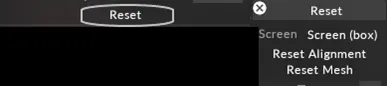
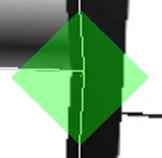 | 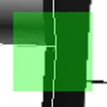 |
| Reshape Alignment Point | Alignment Point |
Export the mesh
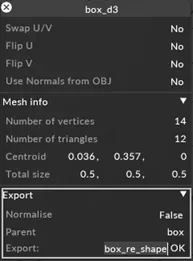
Section titled “Export the mesh”To export a mesh, right-click the mesh in the screen editor to display the mesh editor. Select False for normalise (this will ensure the offset and rotation of your screen is correct when using the new meshes), type a name for the new mesh and click OK. The mesh will be exported to the following folder: output/mesh/filename.obj.
Reset the alignment points
Section titled “Reset the alignment points”- Once the newly reshaped mesh is copied into the Mesh folder, Designer will ingest it into the system, and it should appear in the list of meshes for a screen. Assign these meshes to the projection surfaces.
Once this is done, the alignment points will no longer be valid (because the mesh has changed). - Open the Quick Align editor.
- Select Reset Alignment in Quick Align to remove the alignment points. If necessary, realign the screen using alignment points, but without using the reshape tools.