xR for VR Workflow
The xR for VR workflow enables the production of Spatial Video (VR180 or VR360) content for consumption in Spatial Computing devices from a typical LED xR production stage, using standard broadcast cameras and lenses.
Once the stage and project are set up correctly for xR, a spherical output can be produced in just a few clicks, using a virtual camera.
Demo videos
Section titled “Demo videos”Check out our demonstration of the xR for VR workflow in the two videos below. We recorded simultaneous VR and broadcast outputs, following the process described here.
VR output video
Section titled “VR output video”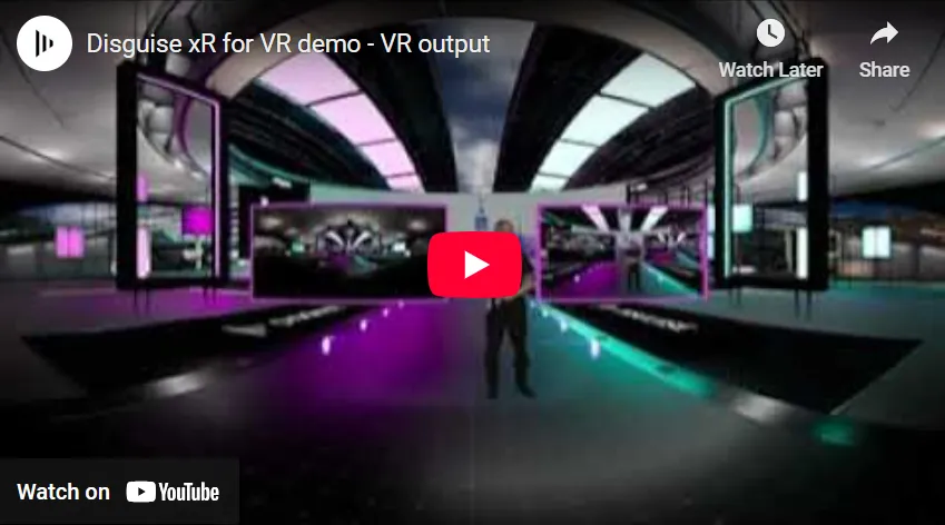
Broadcast output video
Section titled “Broadcast output video”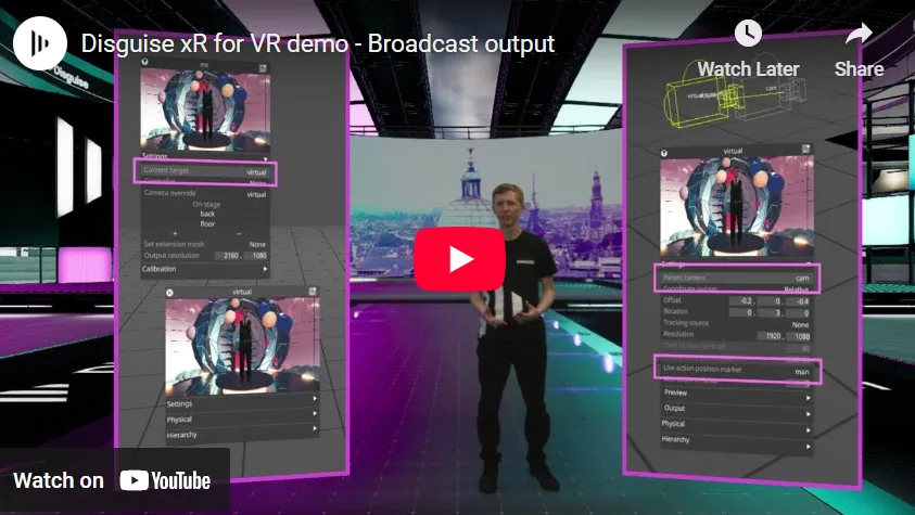
Stage setup
Section titled “Stage setup”The stage must be set up correctly for xR. See xR stage setup for more detailed instructions. In brief, the steps are:
- Create a standard xR LED stage in the Disguise software. Add an LED wall and floor to the stage.
- Add a broadcast camera. In this example, it is called “d3cam”.
- Create an MR set, and add your screens and camera to it.
- Setup and calibrate the stage ensuring lens, colour, and delays are fully calibrated.
- Position your broadcast camera so that it covers all participants on the stage from head to toe. You can preview this in the stage visualiser and use the mouse to pan, rotate, and zoom the stage into view.
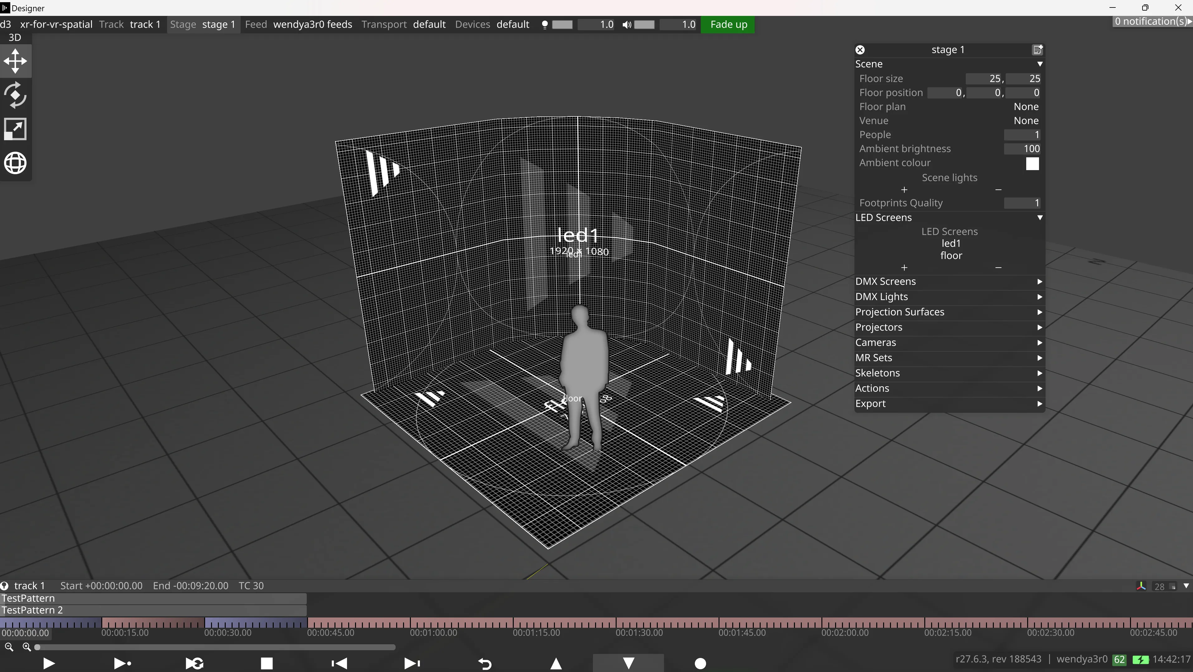
Add and configure virtual camera
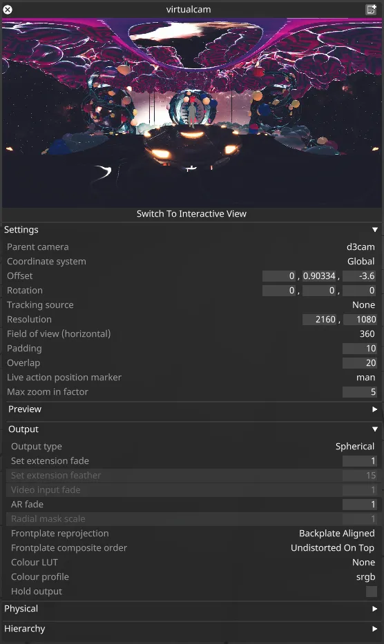
Section titled “Add and configure virtual camera”In Designer, add a virtual camera and configure it as follows:
- Add a new virtual camera to the list of cameras in the stage.
- Set the virtual camera as the target of the MR set. This will allow you to see how changing the virtual camera properties affect the mapped content.
- Set the Parent camera of the virtual camera to the Camera object representing the broadcast camera (d3cam in this example).
- Set the Live action position marker to an object in the stage positioned at the average position of real on-stage people and props, for example at the position of the main presenter. This is necessary to to avoid sliding of the people relative to the virtual scene as the virtual camera moves.
- Set the Coordinate system to Global, and zero out the pitch (X) and roll (Z) rotations. It is important that the virtual camera pitch and roll rotations are zero in global space, otherwise the camera horizon won’t be aligned with the centre of the output, which may cause the scene to appear misaligned when viewed on VR devices.
- Adjust the Offset and yaw (Y) Rotation of the virtual camera to the desired position. This can be anywhere, although if it is positioned at too large an angle relative to the parent camera the people captured on-stage may appear flat.
- Expand the Output separator, and change the Output type to Spherical. The camera will now output a VR360 spatial video feed.
- If desired, the Field of view (horizontal) can be set to 180 for a VR180 output.
- Set the Resolution of the virtual camera to the desired output resolution of the camera.
Avoiding seams in content
Section titled “Avoiding seams in content”Rendering of the spherical content is achieved under the hood by rendering the 6 faces of a cube, then combining and warping them to the correct spherical output. Certain screen-space effects used when rendering the virtual scene can cause visible seams between the faces. See UE scene optimisation for tips on how to avoid this in Unreal Engine.
If some screen-space effects are required for creative reasons, it is possible to mitigate their effects and avoid seams by setting Padding and Overlap in the virtual camera:
- Padding: This value sets a number of additional pixels which are rendered outside each face, then cut away when combining the faces. This can be used to mitigate effects such as blur which exhibit edge effects on the extremities of the rendered image.
- Overlap: This value also renders additional pixels outside each face, then smoothly blends between the pixels of adjoining faces on each edge. This reduces the appearance of seams between faces by smoothing over the join, so you don’t get a hard line.
Add VR180 or VR360 Content
Section titled “Add VR180 or VR360 Content”Using RenderStream
Section titled “Using RenderStream”- Add a RenderStream Layer to your track.
- In the RenderStream Layer Editor, select your VR180 or VR360 asset, such as an Unreal project.
- Add a Cluster Pool of render nodes on the layer.
- Add a Channel, and set the mapping to the backplate of the MR set.
- Start the Workload.
Using other 3D modules
Section titled “Using other 3D modules”Other modules which render 3D content can also be used for spherical camera outputs, such as locally hosted Notch blocks, or the Stage Render or 2.5D layers. Simply set the module mapping to the backplate of the MR set while the virtual camera in Spherical mode is set as the MR set’s target.
Using a video layer - static camera
Section titled “Using a video layer - static camera”If you are not planning on moving the virtual camera, then it is simple to map video content to the camera:
- Add the video to the project folder. The video should be equirectangular content, formatted in the same way as the intended spherical camera output.
- Add a Video layer, and select your media.
- Set the video layer mapping to the backplate of the MR set.
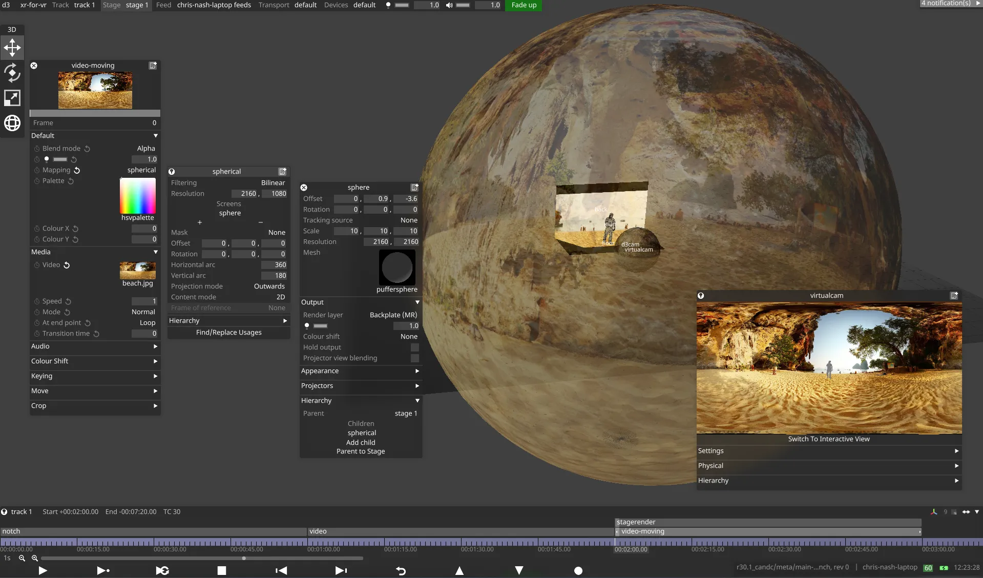
Using a video layer - moving camera
Section titled “Using a video layer - moving camera”If you want to add video content while also having the flexibility to move the virtual camera, you will need to map the video to a spherical mesh, and use the stage render layer to map this to the MR set backplate.
Add a spherical mesh:
Section titled “Add a spherical mesh:”- In the Stage editor, create a virtual projection surface, name it “sphere”, and select the puffersphere mesh.
- Scale the sphere to a large value, e.g. (10, 10, 10)
- Set an appropriate resolution for the video content
- Set the virtual projection surface to Backplate (MR) in the Render layer.
- Set the position of the sphere to the desired eye point of the content (not too far from the position of the camera)
Map the video to the spherical mesh:
Section titled “Map the video to the spherical mesh:”- Add a video layer and select the desired content.
- Create a new spherical mapping, and set this as the mapping for the video layer
- Set the resolution of the spherical mapping appropriately for the content
- Add the sphere projection surface to the list of screens in the spherical mapping
- Set the spherical mapping as a child of the sphere projection surface, under Hierarchy in the projection surface editor
Add a stage render layer:
- Add a StageRender layer to the timeline.
- Set the Render layer to Backplate.
- Map the StageRender layer to the MR set backplate.
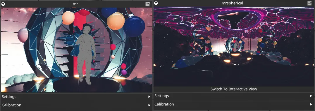
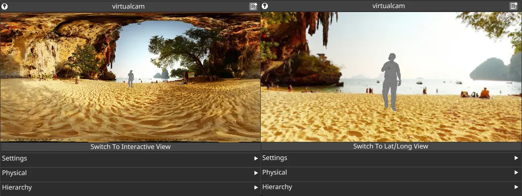
Viewing the content
Section titled “Viewing the content”To preview the spherical camera output within Designer, you can use the ‘interactive view’ in the camera widget. When the Output type of a virtual camera is set to Spherical, A button will appear below the camera preview allowing you to Switch To Interactive View. By default the camera preview will show the equirectangular Lat/Long output image. Switching to the interactive view gives an interactive perspective view of the scene, which can be navigated by holding the left mouse button within the preview and moving the mouse.
Simultaneous spherical and regular outputs
Section titled “Simultaneous spherical and regular outputs”Sometimes it may be desirable to output a regular perspective camera output alongside a spherical output, to produce a traditional broadcast feed alongside a feed for consumption in VR. Since spherical and regular cameras both project onto the screens from the same eye point, it is possible to produce both types of output simultaneously from a single broadcast camera.
To output spherical and regular outputs simultaneously:
- Set up the stage and configure a virtual camera in Spherical output mode, as described above.
- Create a second virtual camera, in Regular output mode.
- Set the Parent camera and Live action position marker in the second virtual camera to match those in the first.
- Make the second virtual camera a child of the first (from the Hierarchy separator), so that both cameras have the same position and rotation.
- Set the other properties of the second virtual camera as desired.
- Creating a second MR set, add the LED screens, and set the second virtual camera as the target.
- Map any content to the backplates of both MR sets. This may require duplicating layers to enable mapping the content to two mappings with different resolutions. However, in the RenderStream layer this can be achieved by adding a second channel.
- Ensure the content mapped to the Regular output is above the content mapped to the Spherical output. This is because the content projected onto the screens is likely to appear at higher resolution for the Regular output.