Example 3 - DNA Spiral
This case study shows how to prepare a spiral shaped LED screen constructed from pucks for Designer. As explained in the previous case studies, the first step is to UV map the 3D model by unwrapping the mesh into a grid.
How the UV map is generated
Section titled “How the UV map is generated”The DNA spiral’s UV map was generated using a combination of techniques applied to the MiSTRIP Star and the OLite Column.
However, the key difference here is the UV map contains gaps. This is because the content creator required a 2D template
that accurately represented the 3D model. In this case, virtual gaps were included to represent the physical gaps
between the pucks.
The UV map of the DNA spiral
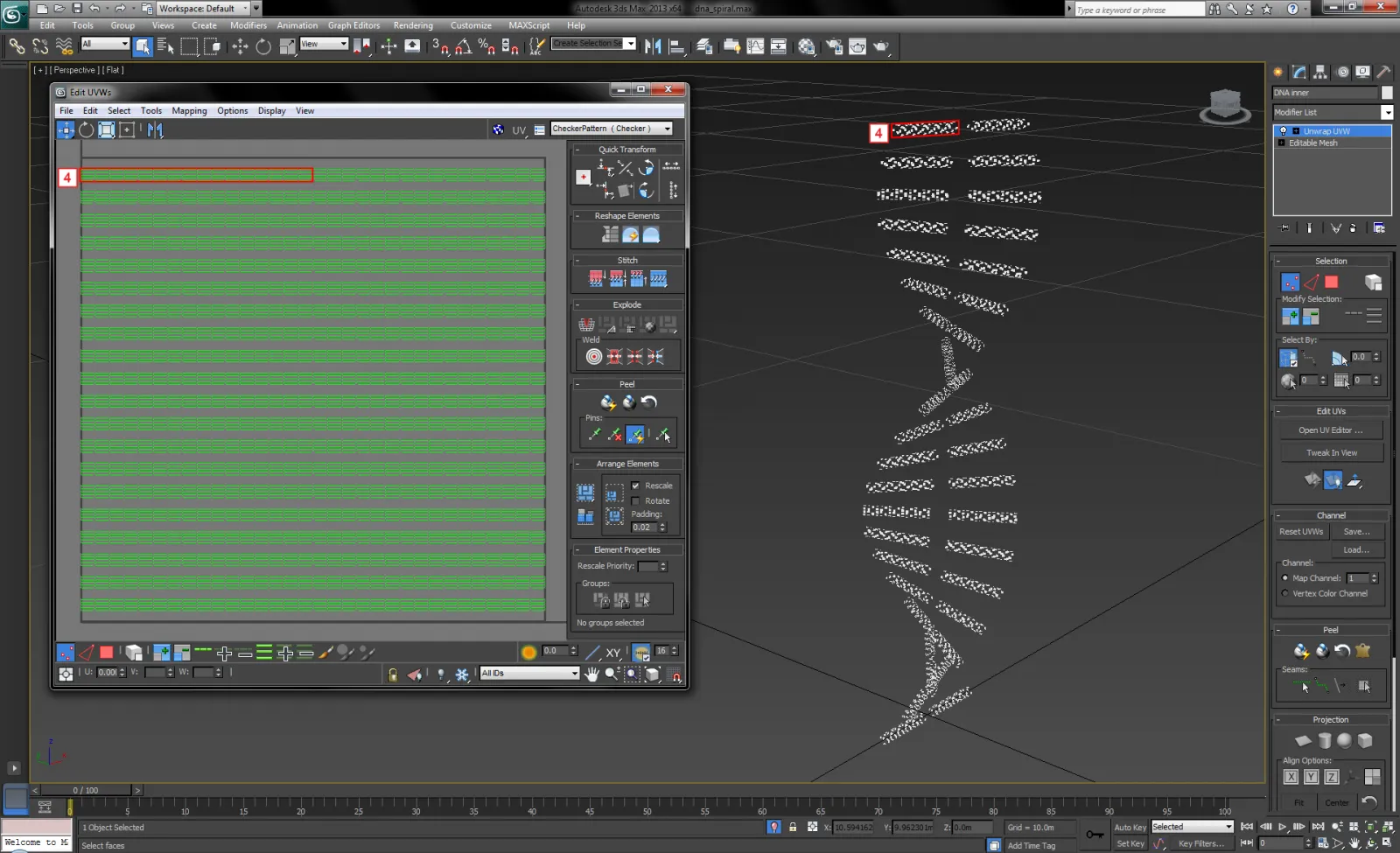
Section titled “The UV map of the DNA spiral”The left-image below shows a content template Direct mapped to the screen in Designer, which was exported as an .obj file from Autodesk 3ds Max. The template was rendered from the UV map, and therefore includes virtual gaps to,represent the physical gaps between the pucks.
The Direct map samples the entire UV map including the virtual gaps, but only the UV coordinates assigned to the 3D model will display video content; enabling the content creator to design content using a template which accurately represents the 3D model. However, here the disadvantage is Disguise’s screen will require a higher resolution than the physical screen, which may affect video performance.
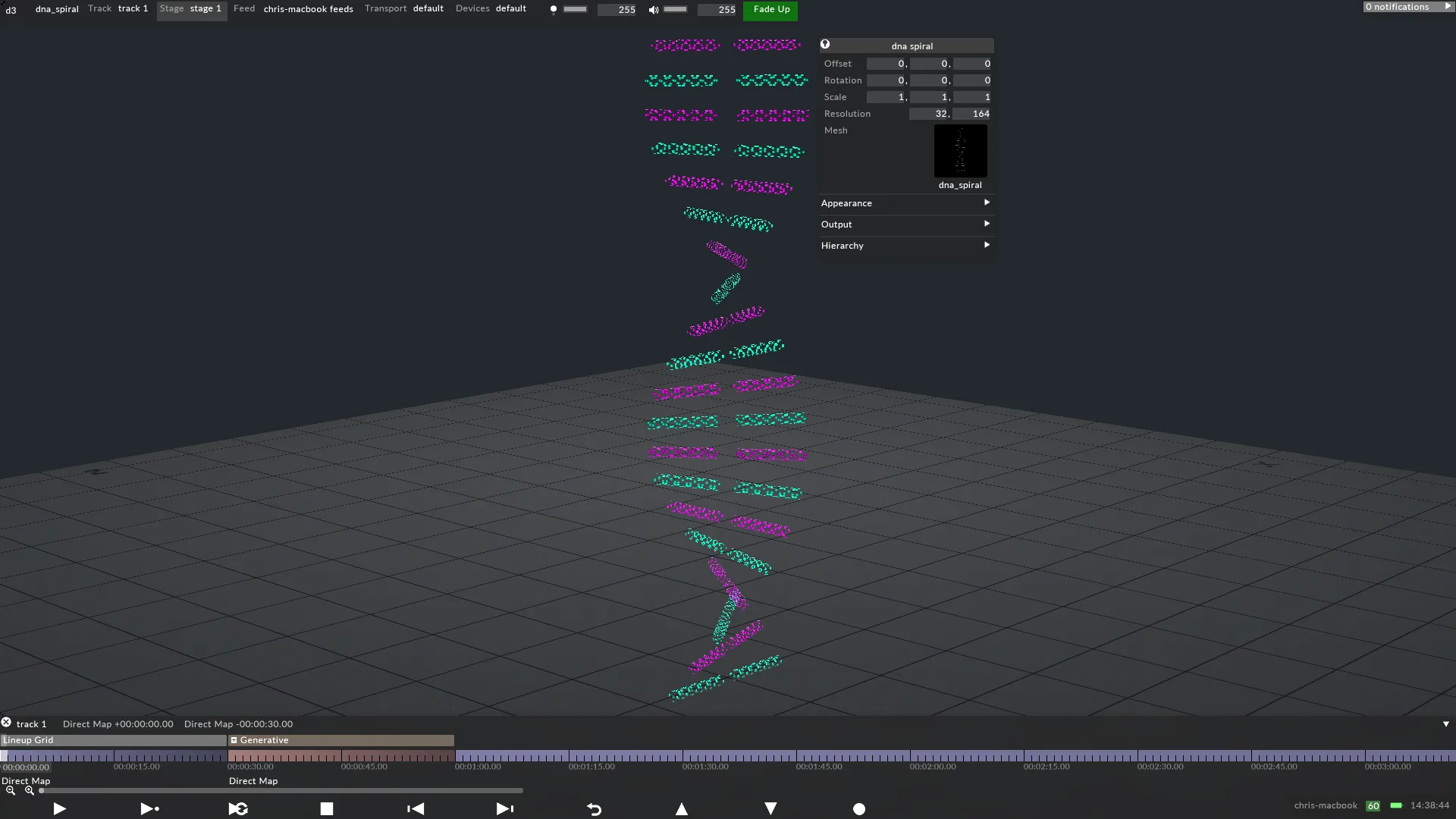
The right-image below shows the Output Feed from Designer to the LED processor. The output is independent of the content, which means the output can be a different resolution. In this case, the content has a resolution of32x164 pixels, but the output has a resolution of 32x82. This is possible because the Output Feeds can be reconfigured, allowing for virtual pixels to be removed from the output, and for the output to be edited to match the LED processor’s pixel map. Therefore, the creative workflow for the content creator is separated from the technical workflow for the hardware technicians, as explained on The UV Map as the Hardware Output page.
Normally, the resolution of the screen in Disguise should exactly match the physical screen’s number of pixels. However, in this case the resolutions can differ. The resolution of 32x164 pixels was calculated by:
- Knowing precisely how many pixels each puck contains horizontally.
- Multiplying this value by the total number of horizontal pucks, to calculate a horizontal resolution.
- Knowing precisely how many pixels each puck contains vertically.
- Multiplying this value by the total number of vertical pucks, and doubling the sum, to calculate a vertical resolution.
In this case:
- 1 puck = 1 pixel horizontally.
- The total number of horizontal pucks is 32. Therefore, 1 pixel x 32 pucks = 32 pixels horizontally in total.
- 1 puck = 1 pixel vertically.
- The total number of vertical pucks is 84. Therefore, 1 pixel x 82 pucks = 82, and 82 x 2 = 164 pixels horizontally in total.
The vertical resolution was doubled because the UV map contains gaps. Importantly, the gaps were spaced evenly to match the heights of the UV shells. Doing so ensures Disguise’s screen will precisely sample the UV map. If the resolution is incorrect the screen will sample virtual pixels, which in turn will display black across the output. Therefore, it is important to generate a pixel-perfect content template to render video content from.