Editing Projectors
This sub-chapter explains the definition of the projector properties. These properties can be edited using the projector editor. To understand how to use the properties please see the sub-chapter Manual Calibration and QuickCal.
Editing a projector
Section titled “Editing a projector”To edit a projector, either right-click directly on a projector in the Stage, or right-click the projector from the screens list in the Stage editor
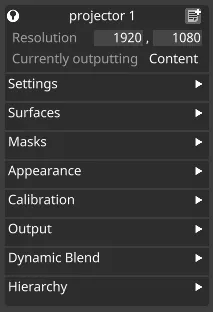
Resolution
Section titled “Resolution”The x and y resolution of the projector, set in pixels. This should ideally be the native resolution of the physical projector model you’re using.
Currently outputting
Section titled “Currently outputting”Type of output mode that currently is active.
-
Content: Outputs the content played on the timeline.
-
Wireframe: Outputs the wireframe of the model.
-
Identify: Full colour image with the projectors name on it.
-
Grid: Outputs a coloured grid applied to the projection object.
-
None: Outputs nothing (except reference points during QuickCal lineup).
Settings
Section titled “Settings”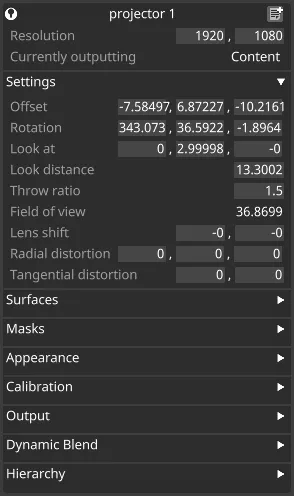
Offset
Section titled “Offset”The x, y and z position of the projector based from the origin point (0,0,0), set in meters.
Rotation
Section titled “Rotation”The rotation of the projector around the x, y and z axes respectively, in degrees.
Look At
Section titled “Look At”The x, y and z position (in meters) of the Look At point. The projector always rotates to point at the Look At point.
Look Distance
Section titled “Look Distance”The absolute distance between the projector position and its Look At position, in meters.
Throw ratio
Section titled “Throw ratio”The throw ratio is defined as the throw distance “D” divided by the width of the projected image, “W”. Since D and W are both in meters, the throw ratio quantity itself has no unit. Simply, the larger the throw ratio, the narrower the focus. Projector lenses are usually rated at particular throw ratios; you would simply type in the lens throw ratio here.
Field of View
Section titled “Field of View”Field of view in degrees for the specified throw ratio.
Lens shift
Section titled “Lens shift”Represents horizontal and vertical lens shift. When horizontal shift is set to 0, there is no shift; when it’s set to 1, the left edge of the projected image lines up with the central projection axis. The same applies to negative numbers (-1 lines up the right edge) and to the vertical shift (bottom and top edges respectively).
Radial distortion
Section titled “Radial distortion”Radial lens distortion coefficients k1, k2, k3
Tangential distortion
Section titled “Tangential distortion”Tangential lens distortion coefficients p1, p2
Surfaces
Section titled “Surfaces”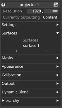
The list of screen surfaces the projector will project onto. The projectors view of the virtual stage will only contain these surfaces. Expanding the Projectors field in a Screen editor will similarly display the list of projectors assigned to that surface.
To add a projection surface to the list:
Section titled “To add a projection surface to the list:”- Left-click the + button to open the Surfaces manager.
- Select the surfaces you wish the projector to see.
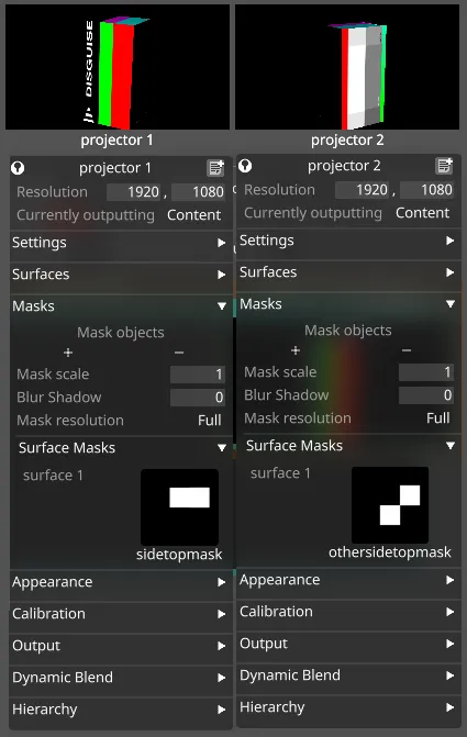
The masks section contains properties for masking the output of a particular projector, allowing certain areas to be excluded from the projection.
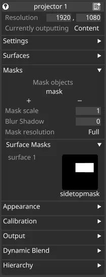
Mask objects
Section titled “Mask objects”The list of objects this projector should render as black.
To add a mask object to the list:
Section titled “To add a mask object to the list:”- Left-click the + button to open the Objects manager.
- Select the objects you wish the projector to mask out (render black)
Mask scale
Section titled “Mask scale”Mask scale allows you to scale the texture that is generated as the mask.
Blur shadow
Section titled “Blur shadow”Blur shadow allows you to add a blur effect to the edges of the generated mask.
Mask resolution
Section titled “Mask resolution”Mask resolution, set to Full by default, allows you to only generate the mask at half and quarter resolution for times when full resolution is not needed, or to save performance.
Surface Masks
Section titled “Surface Masks”Surface masks can be added for each surface assigned to a projector, to control which parts of that surface the projector targets. The masks are applied in the UV space of the surface. Areas which are white in the mask will be targetted by the projector, areas which are black will be masked out.
To assign different faces of a surface to different projectors
Section titled “To assign different faces of a surface to different projectors”- Set up the projection surface and assign it a UV-mapped mesh.
- Set up two projectors targetting the projection surface.
- Create a texture for the surface which is all black, except for the faces which projector 1 should hit which should be white.
- Save this texture into objects/DxTexture in the project folder.
- Repeat steps 3 and 4 for the faces which projector 2 should hit.
- Select the corresponding surface masks in each projector.
- The projectors should each now only output the intended faces of the surface.
Appearance
Section titled “Appearance”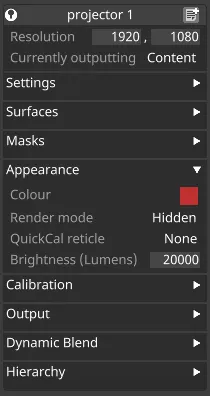
Colour
Section titled “Colour”The colour of the projector beam in the visualiser.
Render Mode
Section titled “Render Mode”Switches the projector’s output in the virtual stage for easier identification of testing.
Types of render mode:
- Hidden
- Beam
- Wire
- Beam & Wire
Calibration
Section titled “Calibration”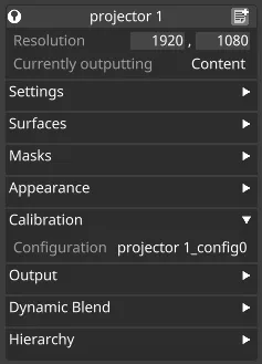
Configuration
Section titled “Configuration”The configuration of a projector stores its calibration - a precise measurement of its actual position and lens settings. Calibrated quantities are not necessarily the same as the properties you enter in the preceding boxes, but will usually match fairly closely.
-
Left-click on the configuration property to open the library of settings for all projectors. You can also create multiple configuration files for the same projector.
-
Right-click configuration to start a QuickCal lineup.
Output
Section titled “Output”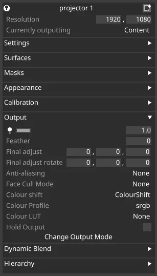
Master Fade
Section titled “Master Fade”Controls the output brightness.
Feather
Section titled “Feather”Shrinks or grows screens in the projector’s view, to fix over-projection.
Final Adjust
Section titled “Final Adjust”Adjust the offset added to a projector’s position, in meters.
Final Adjust Rotation
Section titled “Final Adjust Rotation”Offset added to a projector’s rotation, in degrees.
Anti-Aliasing
Section titled “Anti-Aliasing”The anti-aliasing options for the projector.
- None
- 2X FXAA
- 2X MSAA
- 4X MSAA
- 8X MSAA
Face Cull Mode
Section titled “Face Cull Mode”Use this to skip rendering faces with normals pointing toward (Front) or away (Back) from the projector.
Colour shift
Section titled “Colour shift”The Colour shift property allows you to perform a number of colour-correction operations on the output of a projector.
To apply a Colour shift to a projector:
- Left-click Colour shift to open the Colour shift manager
- Either create a new Colour shift by typing a name into the newcolour shift text box and hit Enter , or select a colour shift configuration from the list.
To edit a Colour shift :
Right-click a Colour shift in the Colour shift manager to bring up the Colour shift editor.
Colour Profile
Section titled “Colour Profile”Colour/gamma space of the output display.
Colour LUT
Section titled “Colour LUT”Cube LUT applied to correct display device output; does not appear in the visualizer.
Hold Output
Section titled “Hold Output”Stops the output of this display until unchecked.
Change Output Mode
Section titled “Change Output Mode”Left-click to change the type of output mode that currently is active.
-
Content: Outputs the content played on the timeline.
-
Wireframe: Outputs the wireframe of the model.
-
Identify: Full colour image with the projectors name on it.
-
Grid: Outputs a coloured grid applied to the projection object
-
None: Outputs nothing (except reference points during QuickCal lineup)
-
BlackTrax: For Blacktrax line up
Dynamic Blend
Section titled “Dynamic Blend”Dynamic Blend is a feature of Designer that enables automatic calculation of soft edge blends across projectors.
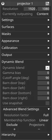
Dynamic Blend
Section titled “Dynamic Blend”Allows you to enable/disable Dynamic blend on individual projectors.
Gamma bias
Section titled “Gamma bias”Adjusts the estimate of this projector’s gamma relative to the Stage’s global blend gamma.
Cutoff Angle (deg)
Section titled “Cutoff Angle (deg)”The Cutoff Angle (in degrees) is a threshold for the angle between the projector’s incidence ray and the normal vector at a pixel.
Any angle equal to or larger than this value will result in zero contribution from this projector for the given pixel.
By default, this value is set to 90 degrees, which means that pixels on a surface that is perpendicular to the projector will have zero contribution from this projector. Using 90 degrees is equivalent to the Dynamic Blend behaviour before the Cutoff Angle was introduced.
Barn door (top)
Section titled “Barn door (top)”Top edge of the Dynamic Blend.
Barn door (left)
Section titled “Barn door (left)”Left edge of the Dynamic Blend.
Barn door (bottom)
Section titled “Barn door (bottom)”Bottom edge of the Dynamic Blend.
Barn door (right)
Section titled “Barn door (right)”Right edge of the Dynamic Blend.
Use Snapshot
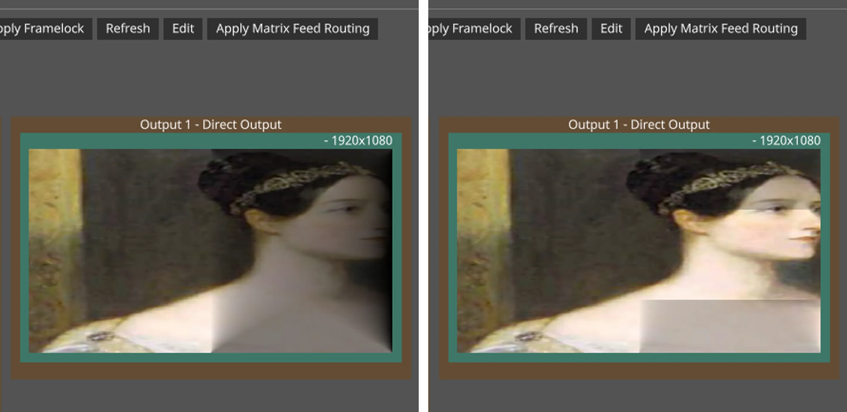
Section titled “Use Snapshot”This allows you to capture a snapshot of the soft edge mask generated by Dynamic Blend, edit it in an external program, and then re-apply it to the projector.
To update the snapshot, you can directly modify the snapshot file: objects/DxTexture/Dynamic Blend snapshots/<projectorName>.tif.
Steps to edit Dynamic Blend mask snapshot
Section titled “Steps to edit Dynamic Blend mask snapshot”- Enable Use Snapshot.
- This will create a DSE mask file (
<projectorName>.tif) in theobjects/DxTexture/Dynamic Blend snapshotsfolder. 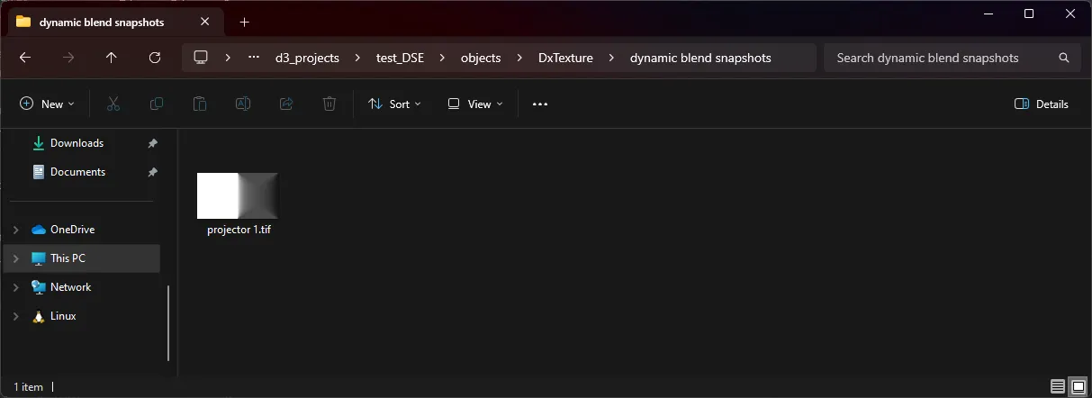
- This will create a DSE mask file (
- Edit the
.tiffile (DSE mask) using an external program (Microsoft Paint is used as an example).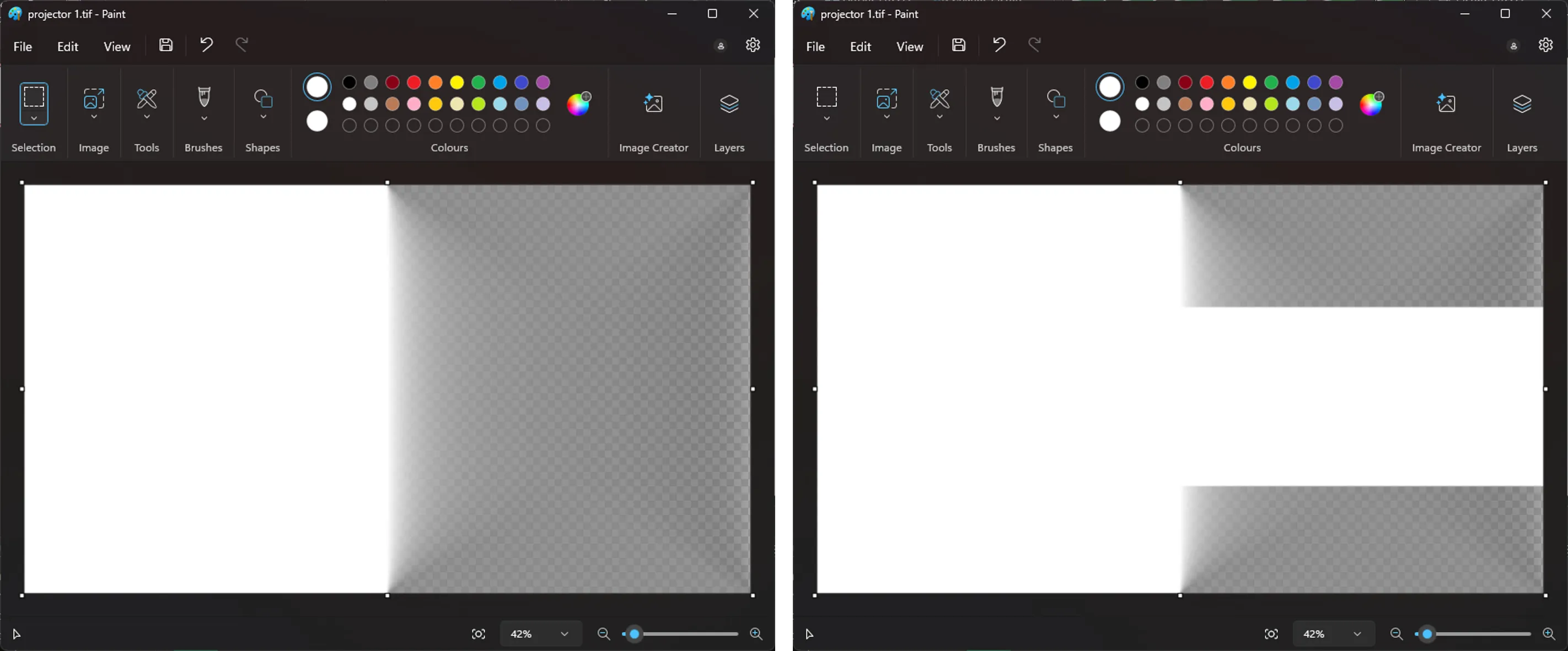
- See the edited mask being updated in D3.
Resolution Factor
Section titled “Resolution Factor”This determines the resolution used for calculating Dynamic Blend projector contributions. The default Resolution Factor value is 1/16th of the projector resolution (i.e. dividing width and height each by 4).
Higher resolutions improve the resulting blend mask, reducing visual artifacts such as overspill. However, this also increases the computational cost of calculating the blend. Projectors should use reduced resolutions if there are regular changes that cause Dynamic Blend to be recalculated.
Any change which affects the spatial relationship between the projector and the projection surfaces will cause Dynamic Blend to be recalculated. Common examples of these changes include:
- Moving or modifying projection surfaces involved in Dynamic Blend.
- Moving or modifying objects used for masks
- Moving or modifying projector properties
Membership Function
Section titled “Membership Function”Linear/Radial/Linear to Radial. This controls how the blend is calculated for the individual projector.
Exclude Projectors
Section titled “Exclude Projectors”Projectors excluded from the Dynamic Blend.
Hierarchy
Section titled “Hierarchy”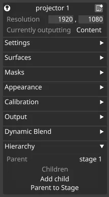
For more information on Hierarchy, visit this link.