Axes
The Axes section of the PositionReceiver Device editor is used to create PositionAxis objects which control the movement of individual screens or props along each axis.
Axes are discrete objects themselves, but can be automatically created by reading the axis data the automation system is sending to Designer.
Creating PositionAxis objects
Section titled “Creating PositionAxis objects”To create a object:
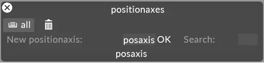
- Select the + button within the Axes section of the editor, type the name of the new object into the text field and hit Enter.
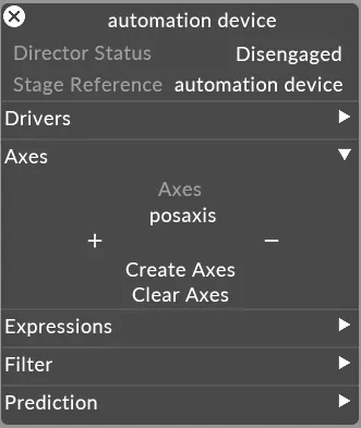
- Click the Create Axes button to automatically read the incoming axes from the Automation driver.
Axis Properties
Section titled “Axis Properties”Configuration
Section titled “Configuration”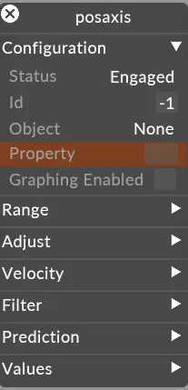
Status
Section titled “Status”Axis ‘Engage’ and ‘Disengage’ options. Allows the user to allow/disallow stage objects being updated in the visualiser. Can also be used during calibration to prevent automation data passing through to the stage objects.
The unique identifier for the axis normally being sent by the automation system. In r14.2 onwards you shouldn’t have to edit this field
Object
Section titled “Object”The Screen that the automation is affecting, ie Surface 1.
Property
Section titled “Property”Which property of the stage object will be automated. E.g. offset.x, offset.y, offset.z, rotation.x, rotation.y, rotation.z.
Graphing Enabled
Section titled “Graphing Enabled”Allows the user to switch on/ off the graphing/ monitoring of incoming packet data (position/ velocity) and filtered position data.
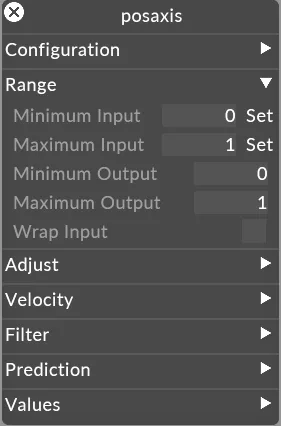
Minimum/Maximum Input
Section titled “Minimum/Maximum Input”Maximum/ Minimum Input: Set the Min and Max Input in Designer to the real world values coming into the software from the automation system. The set button for Maximum and Minimum Input fields can be used to mark the in and out positions (range) of the automated object. This will reference the current Input Value and therefore when pressed it will paste the current input value into the field. Therefore, making it easier to set these values. Designer works in metres and degrees so the user should set appropriate scaling if the received values are not in metres.
Minimum/Maximum Output
Section titled “Minimum/Maximum Output”The Minimum and Maximum Output fields allow the user to scale the input range to a local range in the visualiser.
Wrap Input
Section titled “Wrap Input”Wrap input allows the user to specify that the automated object has rotary motion and the data will wrap. For example, a revolve going from 0-359 and wrapping back to 0.
Filter
Section titled “Filter”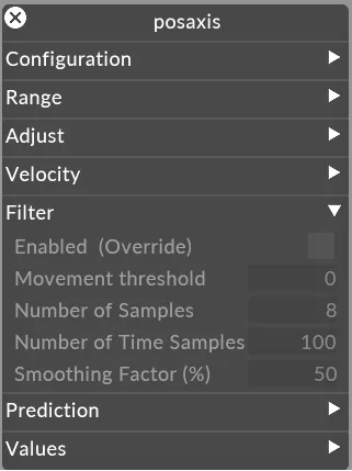
Enabled (override)
Section titled “Enabled (override)”Default - Off
When switched on, filter parameters override the parent devices parameters.
Movement threshold
Section titled “Movement threshold”Minimum change needed before updating output value. This helps when data has unwanted movement when intended to be static. 0 means no threshold (disabled).
Number of samples
Section titled “Number of samples”Number of samples to filter. Use 0 to disable. More samples will introduce higher latency with more smoothing effect. Fewer samples will introduce less latency with less smoothing effect.
Number of time samples
Section titled “Number of time samples”Number of time samples to filter. Use 0 to disable. More samples will introduce higher latency with more smoothing effect. Fewer samples will introduce less latency with less smoothing effect.
Smoothing factor
Section titled “Smoothing factor”Smoothing factor %. Higher values will smooth the data more but will increase latency and therefore the need for prediction.
Velocity
Section titled “Velocity”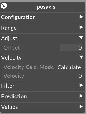
Velocity Calc Mode
Section titled “Velocity Calc Mode”This is for prediction and determines the method for calculating the speed between samples within Designer in order to predict the position ahead of time. When in Calculate mode, Disguise will calculate the speed between the latest and previous packet. When From Packet is selected, the speed information should be received within the packet itself.
Velocity
Section titled “Velocity”Updates only when in Calculated or From Packet modes and displays the velocity that is being calculated/ received from the automation system for the axis.
Prediction
Section titled “Prediction”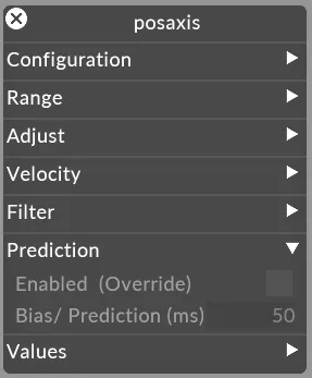
Enabled (override)
Section titled “Enabled (override)”When switched on, prediction uses the bias roperty to predict tracked positions at a future time.
Bias/Prediction (ms)
Section titled “Bias/Prediction (ms)”Compensate for time latency between received data and projector output. Use 0 to disable.
Adjust
Section titled “Adjust”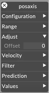
Offset
Section titled “Offset”Allows the user to offset the position of the object relative to the incoming position data.
Values
Section titled “Values”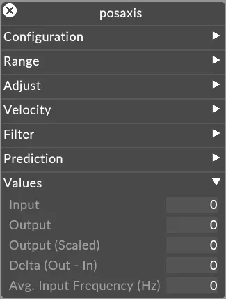
The values of the incoming data, from here one can determine the Min and Max Input of data.
Output
Section titled “Output”The output including any prediction.
Output Scaled
Section titled “Output Scaled”Scaled output velocity comparing the Input and Output levels.
Delta (in - Out)
Section titled “Delta (in - Out)”The difference between the incoming position data and output position data. For good output should be twitching between -0 and 0 value.
Avg Input Frequency (hz)
Section titled “Avg Input Frequency (hz)”The field displays the average frequency that automation data is being received for the axis. It’s important to monitor this field and ensure that the rate is at least 30 Hz or higher and consistently at the rate specified by the automation system. I.e. avoid large swings/ fluctuations in the input frequency.