The UV map as the Hardware Output
Direct mapping means that content is being applied directly onto the UV map of the screen’s mesh, inside Disguise’s visualiser. But the UV map itself, set to the assigned resolution by the screen editor also turns into the output that can be added to the displayhead and further sent to the LED processor. The output is captured by the processor pixel per pixel and sent to the physcial LED technology. As LED processors only can capture strict rectangular outputs it is therefore necessary to generate a precise grid-like UV map for LED screens.
Creative and Technical workflow separation
Section titled “Creative and Technical workflow separation”With Designer’s advanced capabilities of mapping surfaces in various ways (using the different Mapping types), you are not bound not to make content only according to the layout of the UV map or resolution of the screens. Content can for example be virtually projected using a Parallel map, Perspective map, Cylindrical map, Radial map, or re-distributed using a Feed map. Only when using a Direct Map the content is applied directly onto the UV coordinates. When virtually projecting the content onto the pixels using a Parallel map the content instead gets “baked” it into the respective UV maps of all screens included in the map while the output always stays in the format of the UV maps.
With this unique system, you can use multiple content templates (i.e. mapping types) throughout your project while the outputs always stay in the same format defined by the UV map of the screens. As a result of this the content workflow and the technical output get separated; the content people can work from content templates that don’t reflect the layout of the outputs.
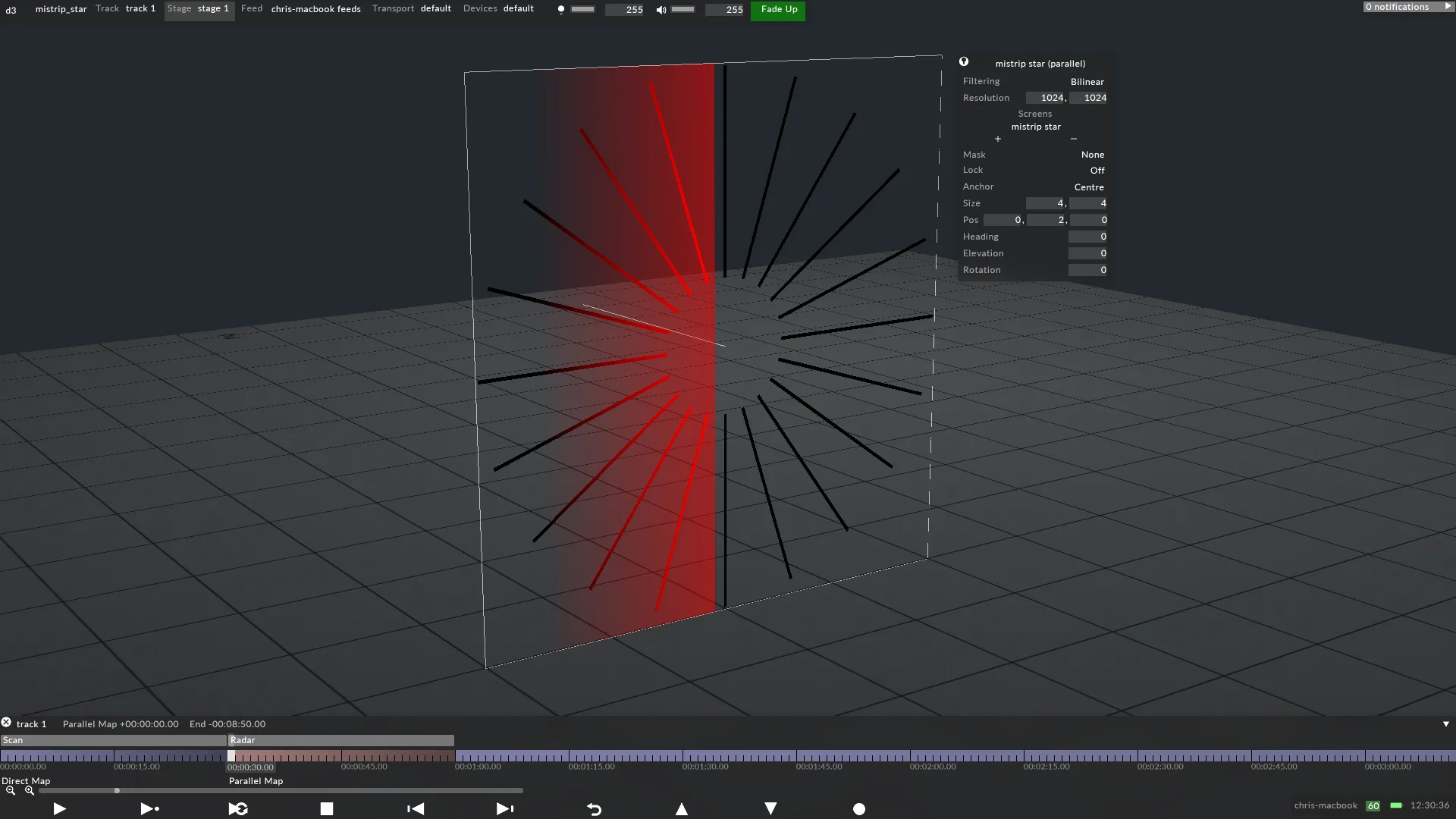
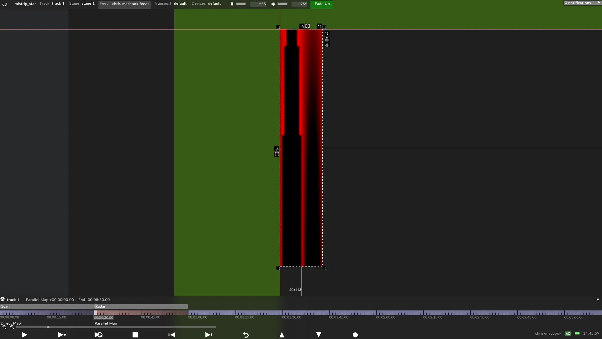
In the example below a screen made of 20 MiStrips receives content from a Parallel map. The Parallel map virtually projects the content into the UV coordinates of the object, i.e the content gets baked into the UV coordinates as explained above. However, the output is still in the format of the UV map and is to be captured by a LED processor.

Content rendered out onto a display head for an LED processor to receive from Disguise.
Re-configure the outputs
Section titled “Re-configure the outputs”If the output does not match the LED processor’s specifications, it can be reconfigured using Disguise’s quick editing controls including the ability to re-position, chop, mirror, and rotate the output.
This allows for even more freedom and separation between the creative and technical workflow.

Same example as above but the output has been reconfigured using Disguise’s quick editing controls.