EVO
Disguise is a workflow platform, designed to be flexible and enable you to interoperate multiple functions within the platform to create your own workflows. One example of this is a collection of workflows known as EVO.
EVO (External Visualiser Overlay) is in essence two parts. An incoming video stream (NDI®) from a third party visualiser, and sharing of camera coordinates between the Disguise camera and the external visualiser’s camera.
By combining these two workflows, you are able to create a seamless link between the two systems - essentially visualising the lighting and video systems together in one viewport.

Watch online: https://www.youtube.com/watch?v=hGaobtrId40
NDI® Video Stream Setup
Section titled “NDI® Video Stream Setup”To set up the NDI® stream:
- Start the NDI® Screen Capture on the lighting visualiser PC.
- In the third party visualiser, set all video surfaces & props to render as black. It might be helpful to use the Export Stage to FBX option in Designer to export the stage directly into the visualiser, to ensure all objects are scaled identically.
- Start the Designer project.
- In Designer, create a new camera and position it as required. This will become your main visualiser camera, so you may also need to increase the resolution if you are running a 4K GUI (the new camera will default to 1920 x 1080.
- Select the visualiser camera to be that new camera in the Stage menu.
- In the Video Input Patch, map one of the Video Inputs to the incoming NDI® stream from the visualiser PC. Check with the preview function that this is routing correctly.
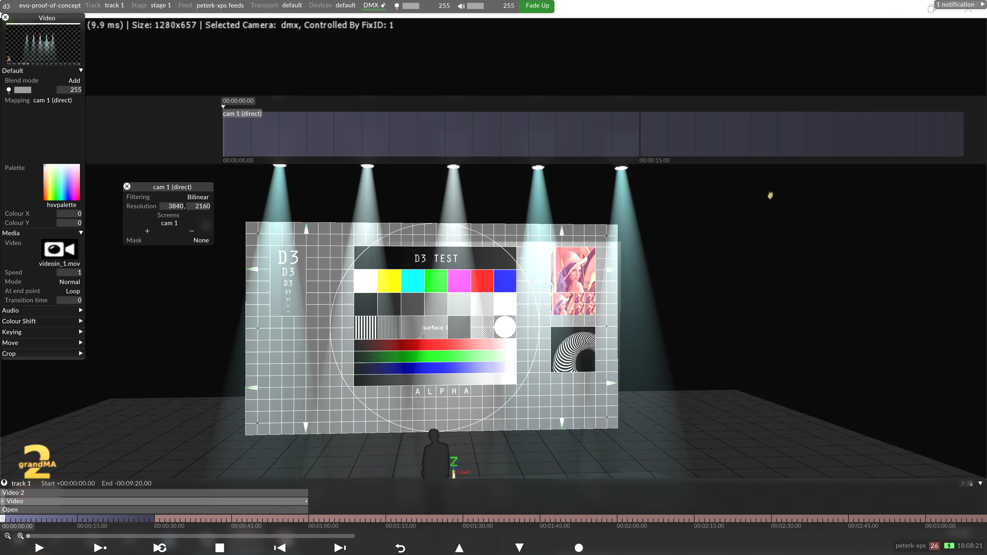
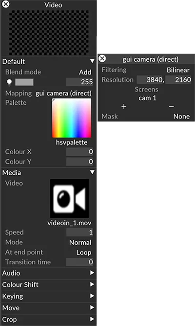
- Add a new Video layer to the timeline.
- In the Video layer, select the Video Input clip as the media asset.
- Set the Video layer to the Add blend mode.
- Create a new Direct mapping and add the new camera you created to that mapping.
- Select the new mapping as the mapping for the video layer.
At this point the incoming NDI® stream from the external visualiser will be overlaid from the Disguise visualiser. If you manually line up the two cameras, this is all that is needed - but using the tracking and control modules in Designer it’s possible to link the two cameras together, via open protocols (DMX, OSC etc).
Camera Position Setup
Section titled “Camera Position Setup”To set up the camera position - there are two options - either Disguise can receive the camera position from the visualiser, or the visualiser can receive the position from Disguise.
Below are generic instructions for both setups. Specific instructions for each visualiser are available on the relevant page for the specific visualiser you are working with.
Visualiser receiving position from Disguise - via DMX
Section titled “Visualiser receiving position from Disguise - via DMX”In this setup, moving the Disguise camera will move the visualiser camera, leaving the Disguise operator in control of what is being looked at.
- Add a DMX device to the project, and patch it to Output DMX.
- Create a DMX lights screen and assign it to create an appropriate number of DMX addresses.
- Add an DMXLightsControl layer to the timeline.
- Select the DMX lights screen as the mapping for the DMXLightsControl layer.
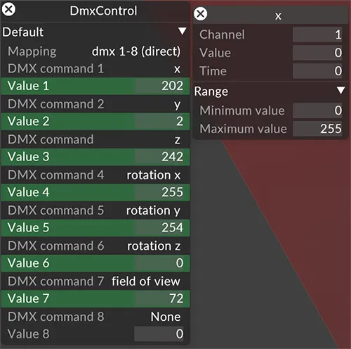
- Use an arrow to connect the control layer to the stage camera (the expression syntax created is
camera:{camera name}.offset.x). - Set up the appropriate commands to send from Designer to the visualiser - note that the DMXLightsControl layer sends only 8 bit values so you will need to convert these to 16 bit or 24 bit depending on the external visualiser requirements. See below.
- Apply any scale factors needed in the expression to center the two worlds. You will need multiple DMXcontrol modules to send all the properties of the camera.
- Patch the external visualiser according to the data stream you created.
Disguise receiving position from the visualiser - Open Layer workflow
Section titled “Disguise receiving position from the visualiser - Open Layer workflow”- Add a DMX device to the project file, and patch it to Input DMX.
- Add an Open layer to the timeline.
- Hold down Alt and drag an arrow between the Open Layer and the Cameras position and rotation properties. This will connect the Open layer to the camera Position & Rotation, enabling control of them from the timeline.
- Right-click on each property and use an expression to connect each of these properties to the appropriate incoming DMX value - you may need to scale these values to match the world-scaling in the third party visualiser.
Disguise receiving position from the visualiser (or lighting console) - PositionReceiver workflow
Section titled “Disguise receiving position from the visualiser (or lighting console) - PositionReceiver workflow”For specific visualiser setup instructions, refer to the relevant page for the visualiser you are working with.