Camera Properties
Cameras can be configured according to the properties of the real-world cameras they represent.
To create a camera and amend camera properties:
- Open the stage editor by right-clicking stage from the dashboard or by right-clicking the floor in the visualiser.
- Expand the Cameras tab.
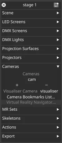
- Right-click a camera from the list or create a new one.
- Adjust the desired properties of the camera using the editor.
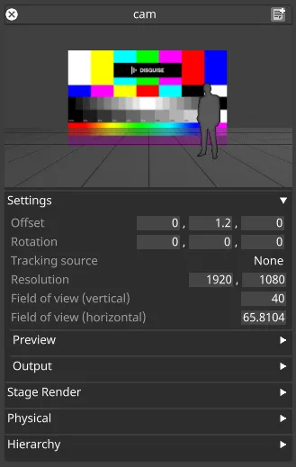
Settings
Section titled “Settings”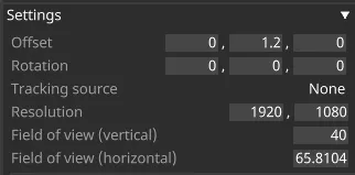
Offset
Section titled “Offset”The offset in meters of the camera’s position from its parent. When parented to the stage which is the default this is the camera’s world position.
Rotation
Section titled “Rotation”The rotation transformation in degrees from its parent. When parented to the stage, which is the default, this is the camera’s world rotation.
Tracking source
Section titled “Tracking source”See Object tracking source and Camera tracking for more information.
Resolution Source (visualiser camera only)
Section titled “Resolution Source (visualiser camera only)”- Take from GUI - Default, Use the resolution of the GUI display.
- Fixed - You can specify a custom resolution. Will not change the resolution of the display, only the camera’s view.
Resolution
Section titled “Resolution”The resolution that the camera will use to render its view.
Field of view (vertical)
Section titled “Field of view (vertical)”The vertical field of view in degrees of the camera.
Field of view (horizontal)
Section titled “Field of view (horizontal)”The horizontal field of view in degrees of the camera.
Preview
Section titled “Preview”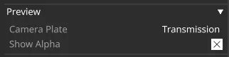
Camera plate
Section titled “Camera plate”Sets the camera preview to Transmission, Backplate, or Frontplate.
Show Alpha
Section titled “Show Alpha”Toggles whether the camera preview will show Alpha or not.
Output
Section titled “Output”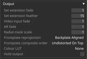
Set extension fade
Section titled “Set extension fade”Opacity of the set extension.
Set extension feather
Section titled “Set extension feather”Feather of the set extension. This is defined as the width of the feather in pixels.
Video input fade
Section titled “Video input fade”Opacity of the video input in the full camera composite. Helpful if you want to see how well the set extension is lined up.
AR fade
Section titled “AR fade”Opacity of the AR (frontplate) content. Helpful to see how well the AR content is lined up.
Radial mask scale
Section titled “Radial mask scale”Applies a radial mask to the film content. This can be helpful to remove excessive radial distortions, particularly for Virtual cameras.
Frontplate reprojection
Section titled “Frontplate reprojection”-
Backplate aligned: Front plate is delayed and reprojected with the backplate so frontplate and backplate content are displayed in sync. This is the default.
-
No reprojection: Frontplate is delayed along with the backplate content but is not reprojected. This is used for frontplate content that aligns more with the filmed content.
-
Minimal latency: Backplate image and frontplate images are taken from two different points in time. This results in the latest frontpate frame being displayed.
Frontplate composite order
Section titled “Frontplate composite order”Defines how content assigned to frontplate is ordered in the composite stack.
Colour LUT
Section titled “Colour LUT”Defines which LUT is applied to the camera. Designer has a number of LUT files built in.
Hold output
Section titled “Hold output”Hold output freezes the current frame of the camera output. This is a toggle setting.
Stage Render
Section titled “Stage Render”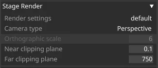
Render settings
Section titled “Render settings”Stage render settings control how cameras render the virtual stage. Right-click on default to open the default configuration; left-click on default to open the StageRenderSettings list manager to create a new configuration or recall an existing one. See Stage Render Settings for more information.
Camera type
Section titled “Camera type”- Perspective - Perspective view.
- Orthographic - Orthographic view.
Orthographic scale
Section titled “Orthographic scale”Orthographic cameras have no concept of depth and distance from the scene. A zoom-like effect can be achieved by adjusting the Orthographic scale, but this setting is independent from zoom in the equivalent perspective camera.
Near & Far clipping plane
Section titled “Near & Far clipping plane”Any geometry closer than the near-clipping plane or further than the far-clipping plane will clipped (not be rendered). The values are in meters.
Reducing the range of these values can improve shadow quality and reduce shadow acne.
Physical
Section titled “Physical”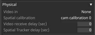
Video in
Section titled “Video in”Defines the live video input this camera is linked to.
Spatial calibration
Section titled “Spatial calibration”Used to create spatial calibration configurations. See Spatial calibration for more information.
Video receive delay (sec)
Section titled “Video receive delay (sec)”Roundtrip latency time calculated from the Video Receive Delay calibration process.
Spatial Tracker delay (sec)
Section titled “Spatial Tracker delay (sec)”Amount of time in seconds between the camera frame arriving and the tracking data associated with it arriving. This is calibrated automatically during Tracking delay calibration.
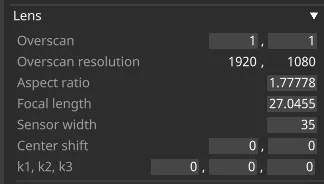
Overscan
Section titled “Overscan”Defines the overscan ratio. The Default is 1. Setting to 1.1 would mean an overscan of 10%. The higher the overscan, the higher the performance impact.
Overscan resolution
Section titled “Overscan resolution”Overscan resolution is the readout value in resolution of the overscan values.
Aspect ratio
Section titled “Aspect ratio”Aspect ratio of lens image.
Focal length
Section titled “Focal length”Focal length of lens in mm.
Sensor width
Section titled “Sensor width”Width of lens in mm, used to normalise focal length and center shift.
Centre shift
Section titled “Centre shift”Center shift of lens in mm, based on sensor size.
K1, K2, K3
Section titled “K1, K2, K3”- k1 - First order radial distortion coefficient, in normalised coordinates.
- k2 - Second order radial distortion coefficient, in normalised coordinates. = k3 - Third order radial distortion coefficient, in normalised coordinates.
The focus parameters are used for depth of field simulations in Designer and RenderStream engines.
Depth of field simulation is applied to stage renders in Designer when the Focus mode is not Disabled. This applies depth of field in camera previews (including the visualiser camera if set), the 2.5D layer and the Stage render layer.
Using lens focus parameters in Unreal Engine
Section titled “Using lens focus parameters in Unreal Engine”- Set up a Renderstream layer with an Unreal asset, with a channel created from a CineCamera.
- Map the channel to a Camera or MR set’s Backplate or Frontplate.
- Start the RenderStream workload.
- Set the Focus mode to Manual or Object tracking.
- Adjusting the lens focus parameters in the camera should cause the depth of field effect to change in Unreal Engine.
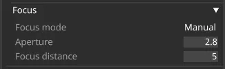
Focus mode
Section titled “Focus mode”- Disabled: No focus effects applied.
- Manual Use focus distance set manually or from tracking source.
- Object Tracking Set the focus distance based on a tracked object.
Focus tracked object
Section titled “Focus tracked object”When in Object Tracking mode, the Focus distance is calculated based on the depth of this object’s centroid relative to the camera.
Focus distance
Section titled “Focus distance”Distance to the focal plane in m. Editable in Manual mode, calculated automatically in Object Tracking mode.
Aperture
Section titled “Aperture”Aperture (f-stop) value, defined as the focal length / aperture diameter.
Prediction
Section titled “Prediction”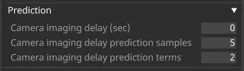
Camera imaging delay (sec)
Section titled “Camera imaging delay (sec)”The amount of time between Designer outputting the frame and capturing the image. Prediction is turned off when this value is zero. If you want to turn prediction on, increase this value until the image looks good. Do not increase beyond the Video Receive Delay value.
Camera imaging delay prediction samples
Section titled “Camera imaging delay prediction samples”How much of the history of the tracking data to predict into the future. Expressed in frames.
Camera imaging delay prediction terms
Section titled “Camera imaging delay prediction terms”How many terms we used to model the movement. Two terms is linear. Three terms is a cubic prediction.
Hierarchy
Section titled “Hierarchy”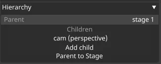
Parent
Section titled “Parent”Shows the parent object (this is usually the stage, so the object will be offset from the origin point of the stage).
Children
Section titled “Children”Shows children of the object.
- Click Add child to create a parent/child relationship between this object and another.
- Click Parent to stage to re-parent the object back to the stages origin point.