OmniCal Mesh Deform
Mesh Deform is an automatic process that enhances the existing 3D model by inserting new vertices based on the aligned point cloud, and adjusting existing vertices accordingly.
OmniCal Stage Plan
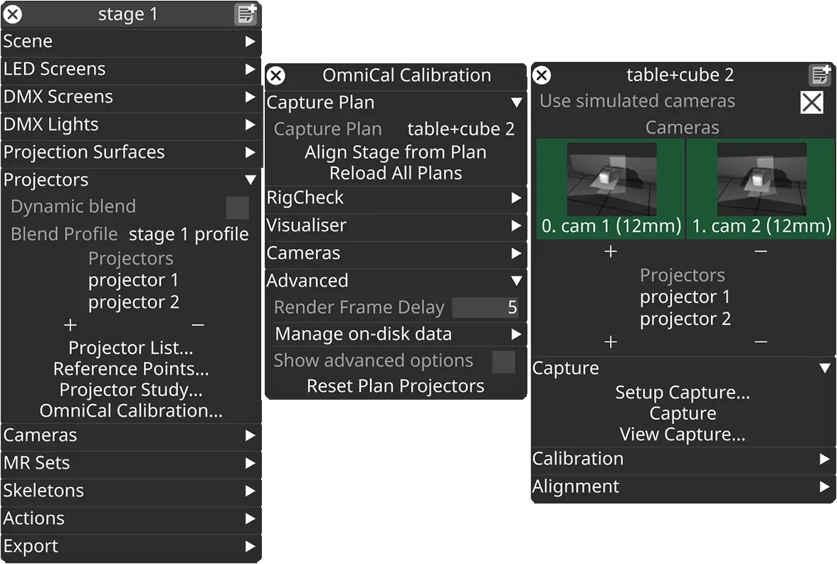
In the Stage editor, under Projectors, click OmniCal Calibration to open the Calibration editor. This widget controls the main OmniCal behaviour. Right-click on any Capture Plan to open its OmniCalStagePlan editor.
In the OmniCalStagePlan we recommend working through the sections from top to bottom: Capture, Calibration, Alignment, and Mesh Deform (if required).
Mesh Deform
Section titled “Mesh Deform”If aligning and reshaping is not enough to make the projection match the physical object, then this is likely caused by shape differences that are not captured in the current 3D mesh. The mesh will need deforming to match the real world object. A typical situation is that Reshape has handled certain vertex deviations, but there are remaining differences like uneven surface areas that are modelled as flat in the 3D mesh, or differences in curvature between the real world object and the 3D mesh.
Mesh Deform is an OmniCal feature that enhances the 3D mesh so it conforms to the captured point cloud. This is achieved by inserting new vertices into the mesh, and splitting triangles accordingly. The new vertices are based on points in the captured and aligned point cloud. Finally, a sophisticated smoothing algorithm adjusts all existing vertex coordinates according to their neighbours (including any newly inserted vertices).
Mesh Deform is able to deal with deformations in physical projection objects that are not or not adequately represented in the original mesh. For example it can accurately represent the actual surface of a curved screen, including any imperfections that arise from the construction process.
UV coordinates of original mesh vertices are not affected during Mesh Deform. Any inserted vertices get assigned UVs that are interpolated from their neighbours.
Mesh Deform requirements
Section titled “Mesh Deform requirements”To use Mesh Deform correctly, a few requirements must be satisfied by the original mesh and the current state of the project:
- The original mesh must be “watertight” in areas that belong together.
- If e.g. the North and East wall of a building are not connected in the mesh at their common edge (i.e. vertices are welded together), then they will likely get torn away from each other during Mesh Deform. Vertices with the same 3D position must be welded in the mesh, so that e.g. the top right vertex of the East wall is the same vertex as the top left vertex of the North wall, etc.
- Holes (e.g. for windows of a building) are allowed, but it may be necessary to prevent unwanted deformations that could introduce twists to the window. This can be done by adding AlignmentPoints to the four corner vertices of each window and anchoring them (see Anchor points below).
- The OmniCal and Designer coordinate system must have been aligned, so the captured point cloud and original mesh overlap properly.
- For best Mesh Deform results it is recommended to first use Reshape to get the best possible match between mesh and point cloud.
Mesh Deform settings
Section titled “Mesh Deform settings”Point cloud size and detail
Section titled “Point cloud size and detail”Ideally, Mesh Deform is performed using an OmniCal capture that uses a high number of projected blobs (see grid size). The denser a point clouds is, the more detail it will provide for Mesh Deform. Therefore a larger grid size will provide a more accurate and higher quality deformed mesh. If the physical projection surface does not have many local deformations, then the default grid size is often sufficient.
Dense captures take a longer time to complete and calibrate, so only use a high grid size when a higher quality Mesh Deform is actually needed. When using high grid sizes, it is recommended to use a separate OmniCal plan with lower grid size for faster (e.g. daily) re-calibration. This is especially helpful if the calibration concerns multiple surfaces, but not all require deforming.
Distance threshold
Section titled “Distance threshold”This threshold denotes the maximum absolute distance between a point in the point cloud and the nearest mesh surface, along the point normal’s direction. It is used to decide whether or not to add a new vertex for a certain cloud point (and deform its neighbours accordingly), or not. If the cloud point is further away from the current aligned (and potentially reshaped) mesh than this threshold, then Mesh Deform will not add a new vertex at the cloud point’s 3D position.
This threshold is useful to exclude noisy or irrelevant data from the point cloud, e.g. trees in the foreground.
Default value: 0.1 m
Depending on the size and scale of a physical projection surface, this value may need to be increased or decreased to get better looking results.
Angle threshold
Section titled “Angle threshold”This threshold denotes the maximum angle between the normal vector of a cloud point and the normal vector of the nearest mesh surface. It is used to decide whether or not to add a new vertex for a certain cloud point (and deform its neighbours accordingly), or not. If the angle is larger than this threshold, then Mesh Deform will not add a new vertex at the cloud point’s 3D position.
This threshold is useful to prevent smoothing over edges and corners (e.g. right angles between floor and wall).
Default value: 30 degrees.
Anchor points
Section titled “Anchor points”Anchor points in Mesh Deform are vertices that do not get modified during the smoothing operation. They are used as fixed guides. Any other vertices get interpolated based on the original vertex position, its non-anchor neighbours and the anchor points near it.
Mesh Deform treats all newly inserted vertices as anchor points, since they are directly derived from the captured point cloud. Other vertices (like mesh borders or alignment points) can also be treated as anchor points. This will influence the output mesh, since those vertices will keep their original aligned (or reshaped) position. This can make sense if there is for example a high confidence on the calculated location of reshaped points. But in most cases where Mesh Deform is required this is not desirable, so these options are not enabled by default.
Anchor points can be modified using these settings:
- Lock mesh boundaries: Unlocked / Locked
- Whether mesh boundary vertices are treated as anchor points or not.
- Has no effect on closed meshes without boundary edges, e.g. spheres.
- Default: Unlocked.
- Use alignment points: No, Yes, If aligned in 2+ cameras
- Whether Alignment points from QuickAlign will be treated as anchor points or not.
- The third option only anchors alignment points that are aligned in more than 2 cameras. Having several camera intersections can provide a higher reliability on the calculated 3D vertex position.
- Default: No.
Visualising Mesh Deform
Section titled “Visualising Mesh Deform”You can preview the Mesh Deform results by changing the Point Cloud visualisation mode to Deform in the calibration editor. The results are updated in real-time so you can try out different deform settings using this. The lines indicate where each existing mesh vertex would be moved to. Newly inserted vertices will not be shown, though.
Using Mesh Deform
Section titled “Using Mesh Deform”It is a good idea to try the default Mesh Deform settings first, and carefully inspect the result. If the deformed mesh has included or excluded cloud points incorrectly, then decrease or increase the distance and angle parameters as required and try again.
- Click Mesh Deform… from the Alignment tab of the Plan editor.
- Select the screen you wish to deform by left-clicking the screen property in the deform editor.
- Adjust parameters for this screen, as required.
- Click Deform.
Mesh Deform Performance
Section titled “Mesh Deform Performance”Running a Mesh Deform operation may take a while, depending on the number of vertices and triangles in the original mesh, as well as the size of the captured point cloud.
After clicking Deform, the process will run in the background until it is complete. This may take several seconds (for simple meshes) up to tens of minutes (for complex meshes and dense point clouds). Mesh Deform is very CPU intensive, so although it’s possible to continue using Designer while this is running, the impact on performance is very noticeable.