NMOS in Disguise
Designer will now support using NMOS for ST 2110 video output from IP-VFC cards. We’ve taken the open source code solution developed by Sony named nmos-cpp and extended it to receive display updates from Designer when IP-VFC cards are outputting in ST 2110 format. This will run on each Disguise server when Designer runs to advertise the server as an NMOS node with each IP-VFC card an NMOS device and each ST 2110 stream an NMOS sender.
In summary, each Disguise server runs an NMOS node service that:
- Registers the server itself as an NMOS Node.
- Exposes each IP-VFC card as an NMOS Device.
- Publishes each ST 2110 stream as an NMOS Sender.
- Publishes each IP Video Capture instance as an NMOS Receiver for each machine in the session (e.g. if there are three machines, three NMOS Receivers will be seen for each IP Video to show that an ST 2110 stream can be received by any of those machines)
An active NMOS registry must be available on the network for node discovery and registration.
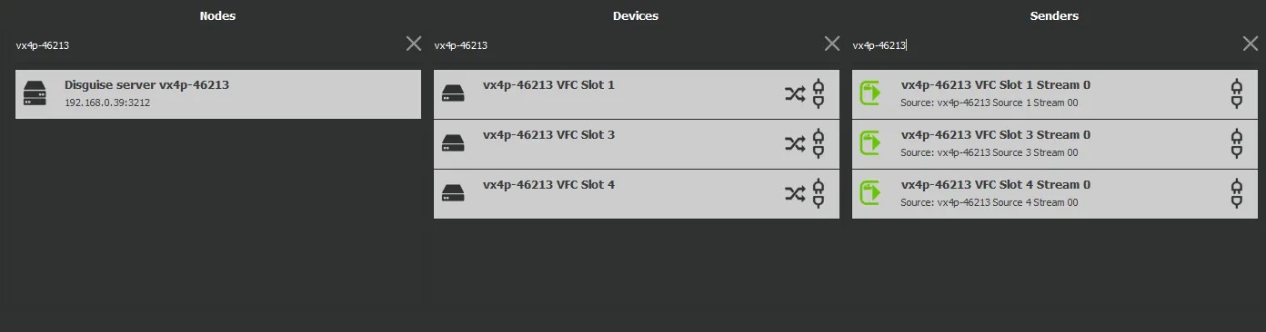
The NMOS Node, Device and Sender information sent to the registry will be presented according to the registry software, but it will look something like this:
Configuration
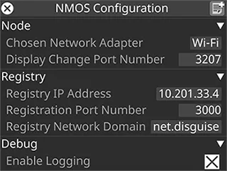
Section titled “Configuration”There’s now an NMOS Configuration widget accessible from the d3 menu. This allows for specific NMOS registry details if the user wants to override the mDNS discovery.
Parameters
Section titled “Parameters”Chosen Network Adapter - This will be the network adapter that the NMOS node uses to communicate with the registry. It’ll also use the IP address of this to advertise its APIs. If this is left blank, it will default to the user selected network adapter in d3Manager.
Display Change Port Number - This is the port Designer uses to send the NMOS node updates in the display. It defaults to 3207 but can be changed if this clashes with something else.
Registry IP Address - If the NMOS node’s auto discovery can’t find the NMOS registry, or is connecting to a registry you don’t want to use, this can be used to specify the IP address of the registry you want to use. If you want to use auto discovery, leave this empty.
Registration Port Number - Once the NMOS node finds the NMOS registry, it will register itself using the registration API. This will be on a specific port number. The default port of 3211 will be used, but depending which NMOS registry it is this can differ, so it can be set here.
Registry Network Domain - If the Disguise server is on a different domain to the registry it can be specified here. If you want to use auto discovery on the same domain, leave this empty.
Enable Logging - Used for debugging but off by default.
Troubleshooting
Section titled “Troubleshooting”1. Check that the NMOS node is running and correctly configured:
Section titled “1. Check that the NMOS node is running and correctly configured:”- If the node is displaying the error “An error occurred reading the nmos-config.json file”, ensure that the file is in correct json format. If there’s a comma missing, or a single quote ” it will mean the whole file will be rejected. This file shouldn’t be edited by users.
- The nmos-node.exe application is run by Designer on start up with the settings in the NMOS configuration widget. You can check various elements of this with a web browser by logging into the node’s APIs.
- Check the node settings in a browser with
http://localhost:3209/settings/all/.- If nothing comes up and it says the site can’t be reached then either the node isn’t running or the settings port has been changed from
3209in the json config file. - If it does display the settings, ensure the registry_address and registration_port and domain are what you configured them to be in the NMOS configuration widget. If they aren’t, restart Designer and they should be passed through on start up.
- If nothing comes up and it says the site can’t be reached then either the node isn’t running or the settings port has been changed from
- Check that Designer is sending messages to the node in a web browser with
http://localhost:3207/displaychange/.- The port number
3207is configurable, so ensure this is correct in the NMOS Configuration widget. - If it says null or is empty the node hasn’t received any updates from Designer yet.
- This could be because it has no ST 2110 outputs. Make sure IP-VFC cards are in ST 2110 mode.
- The IP-VFCs should also have a green border in the feed screen to indicate they’re active and ready. If they don’t, try applying feeds.
- If it does have data it’ll be the last message sent from Designer.
- A field named “last_update_date_time” will show when it received this message.
- It will also show the “hostname” it came from. This message should only ever be sent from Designer running on the same machine as the node.
- It will include a list of NMOS devices, which in this case are IP-VFC cards. Each card can have up to four ports which equate to NMOS senders
- The port number
- Check the node API is advertising its data correctly in a web browser with
http://localhost:3212/x-nmos/node/- This will show the possible schema versions it’s on. By default we use the latest, v1.3
- After selecting the version you’ll see all the device, flow, sender, receiver and source data it’s storing.
- Using
http://localhost:3212/x-nmos/node/v1.3/self/will show the endpoints it’s advertising to the registry.
- Check the SDP file in a web browser with
http://localhost:3215/x-nmos/connection/v1.1/single/senders/<sender id>/transportfile- The
sender idwill look like this803d9129-0000-1000-a000-401175c00600. The second digit, in this case0, is the port number of the IP-VFC card and the last 12 characters are the IP-VFC’s first mac address. The other numbers will always be the same. - The SDP file is a text based configuration file so it’s human readable. You’ll see properties like these which should match the current output of your IP-VFC card:
width=3840; height=2160; exactframerate=60; sampling=YCbCr-4:2:2; depth=10; colorimetry=BT709; - For more detail on what’s expected in these files, see https://en.wikipedia.org/wiki/Session_Description_Protocol
- The
2. NMOS Registry not discovered
Section titled “2. NMOS Registry not discovered”- Verify that an NMOS registry service is running and reachable on the network.
- Confirm that mDNS is permitted across your network. If mDNS is blocked, specify the registry’s IP address and registration port manually in the NMOS Configuration widget and restart Designer.
- Check firewall rules on both the registry host and the Disguise server to ensure the correct ports are open.
- The NMOS settings for auto discovery should have a registry_address of
0.0.0.0and a domain oflocal.. If these fields are empty in the NMOS Configuration widget, the node will default to these.
3. Node not appearing in registry
Section titled “3. Node not appearing in registry”- Are you using ST 2110 video output or input? This could either be with IPVFC cards or IP Video In. The node will only be created in NMOS once there’s a device to advertise.
- Check that the node is running correctly first following the instructions in step 1.
- Ensure the correct Chosen Network Adapter is selected. If left blank, it defaults to the adapter selected in d3Manager, which may not be on the registry subnet.
- If neither the Chosen Network Adapter or the User Selected network adapter in d3Manager are set, the node will advertise itself on all network adapters on that machine. This can have mixed results, as the registry may detect it more than once and become confused about where it’s running. Setting a Chosen Network Adapter will prevent this.
- Confirm that the Registration Port Number matches the registry’s API port.
- Restart d3 after changing configuration settings.
4. NMOS Senders missing or inactive
Section titled “4. NMOS Senders missing or inactive”- Verify that the IP-VFC card is correctly configured for ST 2110 output in Designer
- It will have an NMOS sender for every active VFC port, so if it’s in Quad mode in Designer there will be four corresponding NMOS senders
- Make sure all ports in Designer have a green background in the feeds screen. If they don’t, try applying feeds
5. Streams appear but do not connect
Section titled “5. Streams appear but do not connect”- Confirm PTP synchronization is running correctly on the network. Without PTP lock, ST 2110 senders may register but not pass valid video
- Verify multicast routes are configured correctly on the switch.
NMOS specification coverage
Section titled “NMOS specification coverage”IS-04 - Discovery and Registration
Section titled “IS-04 - Discovery and Registration”- The NMOS node application will run with Designer and connect to an NMOS registry on the network either by multicast DNS “Auto” discovery or to a specific IP Address and registration port number set in the NMOS configuration widget
- The NMOS node will advertise all Designer’s ST 2110 video senders and receivers
- each Disguise server will be listed as an NMOS node
- within that node each IP-VFC card will be listed as an NMOS device
- each IP-VFC port set to output ST 2110 video will be listed as an NMOS sender
- if Designer is using IP Video Capture it will create an NMOS device named IP Video Capture
- under this each IP Video Capture instance will be listed as an NMOS receiver. If they’re created from a sender’s SDP file they’ll use the sender name in their own label. If they’re created with no SDP file they’ll advertise themselves as being capable of receiving a wide range of display properties to allow any NMOS sender to connect to them
IS-05 - Device Connection Management
Section titled “IS-05 - Device Connection Management”- The NMOS node will propagate its local device information to the NMOS registry and connections can be made between senders and receivers on the network
- The node has a Connection API which the registry can push updates to
- If it receives a request from a sender to connect to an IP Video Capture instance it will pass the SDP file contents to Designer, making it immediately ready to use as a logical video input that can be mapped accordingly
- If it receives a request from a receiver to subscribe to a senders output and the request contains multicast IP addresses these will be sent to Designer to update those address on the IP-VFC card. Note that although you’ll see the values change in the VFC port editor, you’ll still need to apply feeds to actually push them to the card itself
- Also, if an IP Video Capture instance is created from an SDP url or from selecting a sender from the NMOS sender list, it will update the connection API on the node to propagate to the registry and the node of the sending device
Schema versions
Section titled “Schema versions”- The NMOS node can support various schema versions depending on the schemas used by the NMOS registry
- Supported registry query schemas: v1.2 and v1.3
- Supported IS-04 schema: v1.2 and v1.3
- Supported IS-05 schema: v1.0 and v1.1