OmniCal Camera Setup
Summary
Section titled “Summary”- GigEVision network setup.
- Install Vimba or Vimba X for Windows.
- Set up camera positions and configure exposure and lens settings.
- Configure cameras in Designer.
- Troubleshoot any network or camera issues.
OmniCal Machine Vision (MV) system
Section titled “OmniCal Machine Vision (MV) system”The camera setup described here must be done before you run Designer.
Network setup
Section titled “Network setup”For information about used network ports, please see Network ports and activity.
Network infrastructure
Section titled “Network infrastructure”The OmniCal MV system is based on the GigE Vision (R) industry standard, which requires a bandwidth of 1 Gbit/s or higher. Camera capture speed scales with the available usable bandwidth. For example, on 10 Gbit/s setups the discovery of MV cameras and the transmission of captured images will be much faster.
The MV cameras are powered via Power over Ethernet (PoE), which simplifies installation by combining power and data through a single Ethernet cable. PoE must be provided either by the network switch or a PoE injector. The power requirement over PoE is quite low at 2.8W.
Ensure that all network infrastructure parts (switches, cables…) match the desired bandwidth and power specifications.
In the case of wired cables (as opposed to fibre), appropriate cables are required for reliable performance over long distances and in the presence of electromagnetic interference (EMI).
Minimum cable type for runs up to 100 meters, depending on network bandwidth:
- 1 Gb/s: Cat 6
- 10 Gb/s: Cat 6A
Multicast considerations
Section titled “Multicast considerations”OmniCal does not actively make use of multicast technology. Therefore, we recommend disabling it in network switches, if possible.
A GigE switch that has multicast enabled will be able to replicate traffic to multiple subscribed GigE Vision receivers. Only the first receiver will be able to control camera parameters; all others can only view image data.
In practice, multicast is irrelevant for OmniCal because only one Director server can run the image capture process and receive the images. The Disguise recommendation is to disable multicast, unless operators require it for purposes other than OmniCal.
Disguise OmniCal cameras support multicast network configurations when configured correctly. Refer to the Switch Setup section for configuration guidance.
Network adaptor settings
Section titled “Network adaptor settings”The following settings need to be set on the network adaptor on the Director server that connects to the switch with the cameras. You may need to update to the latest drivers to see some of these advanced options.
- Jumbo Frames: Enabled
- Packet / frame size (MTU) should be set to 8228 bytes or the largest supported value.
- e.g. 9000 or 9014, depending on whether the adaptor’s driver includes the packet header in the count or not.
- Packet / frame size (MTU) should be set to 8228 bytes or the largest supported value.
- DMA Coalescing: Disabled
- DMA Coalescing can increase latency, so it should be disabled for GigEVision use.
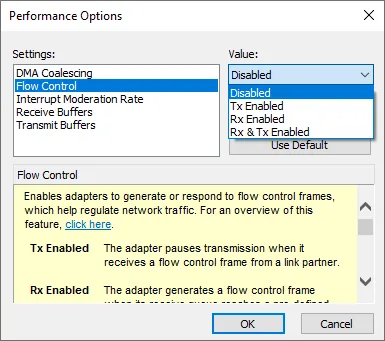
- Flow Control:
- Can usually be left in the default setting.
- In most network situations, enabling Flow Control for Rx/Tx is beneficial; however, it does not improve GigEVision performance for OmniCal cameras.
- If the network adaptor is not exclusively used for OmniCal (e.g. when testing or demoing from a laptop), then Flow Control is best enabled.
- If the network adaptor is exclusively used for OmniCal (i.e. on Disguise servers), then it’s preferred to disable Flow Control.
- In some edge cases, it may be necessary to enable Flow Control to allow stable camera discovery, see Troubleshooting section.
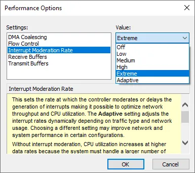
- Interrupt Moderation Rate: Extreme
- This reduces the number of system interrupts, which reduces CPU usage and thus improves performance for high-throughput use cases.
- In some situations (e.g. smaller packet sizes) it may be beneficial to use a less aggressive setting such as High or Adaptive, see Troubleshooting section. This is because a lower interrupt moderation rate makes the system more responsive to incoming packets, which helps when large amounts of individual packets are received (as is the case with packet sizes smaller than 9 kbyte Jumbo frames).
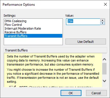
- Transmit buffers: 256 bytes
- The adaptor won’t be sending a lot of data, so set it to 256 bytes or the closest low value that is supported by the driver.
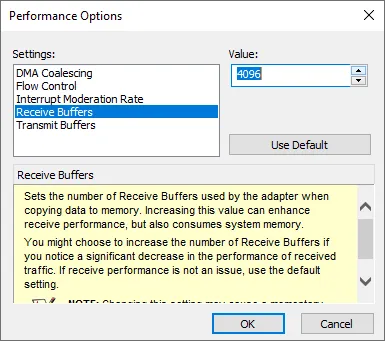
- Receive buffers: max setting available, e.g. 4096 bytes
- This is because the adaptor will mainly need to receive many large packets.
- Receive-Side Scaling (RSS): Enabled
- RSS helps to better balance CPU usage for network events, so it should usually be enabled.
See GigE installation manual for further explanation.
Setting up the network adaptor
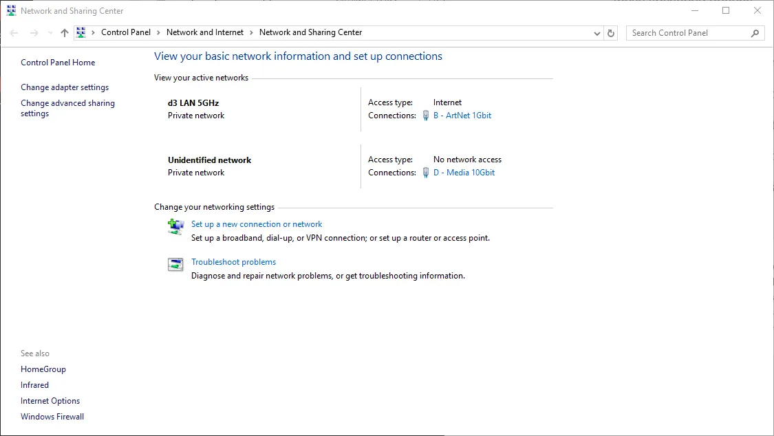
Section titled “Setting up the network adaptor”Using a 1 Gb port on the Director server for the camera communication is sufficient for small numbers of cameras. But a higher bandwidth port (e.g. 10 Gb) is preferred (even on a 1 Gb network), because their max receive buffer size is larger.
- Navigate to the Network and Sharing Center and click to open the D - Media 10Gbit adaptor.
- On the General tab, click to open Properties.

- Enable the following settings and click Configure.
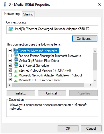
- Select Jumbo Packet and assign it a value of 9014 bytes.
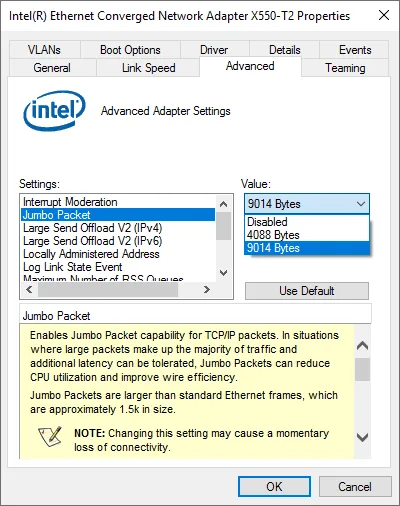
- On the Advanced tab, select Performance Options.
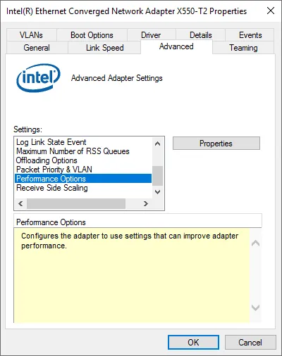
- Set the Interrupt Moderation Rate to Extreme.
- Select Receive Buffers and set it to 4096.
- Select Transmit Buffers, set it to 256 and click OK.
- Select Flow Control and click Disabled or Enabled, as required (see Network adaptor settings).
Jumbo Packets
Section titled “Jumbo Packets”Jumbo Packets allow sending more data in a single packet, for example, 9 kbyte instead of the default of 1500 bytes. This reduces the number of packet headers being sent and increases the amount of actual data sent per second. Therefore, Jumbo Packets increase the overall usable bandwidth, and also reduce the CPU usage on the sender and receiver’s side. Jumbo Packets can be configured for different packet / MTU sizes, typically around 8-9 kbyte. The value quoted by network adaptor drivers or switches can also vary, depending on whether they include any packet headers in the value or not.
Using Jumbo Packets can arguably make a network more fragile to interference, since dropped packets are larger, so resending them requires more work and data. So when using Jumbo Packets, the system should always be set up to minimise dropped packets. In Designer, you can use Plan Camera Stats to check how your system performs regarding dropped packets and frames.
GigEVision protocol requirements
Section titled “GigEVision protocol requirements”GigEVision was chosen as the basis for OmniCal machine vision cameras. It is an interface standard for high-performance industrial cameras on standard low-cost IP networking infrastructure. GigEVision comprises of several UDP-based protocols that optimise for fast image transfer, but do not guarantee packet delivery to the receiver. For video data, it uses a custom packet-resend algorithm, in which packets get dropped altogether if it’s not possible to get a full frame within a reasonable time. If the network is too saturated (e.g. camera bandwidth configured too high) or it experiences interference (other network devices on the camera switch), then some packets or even whole image frames may get dropped, cameras may time out, and in some cases, cameras may even lock up and need to be rebooted.
The Network adaptor settings explained above are required for best performance of GigEVision cameras. In some circumstances, it may be possible to use OmniCal successfully with different settings, but this will likely affect performance and reliability, and is therefore not recommended.
Switch Setup
Section titled “Switch Setup”- Connect a PoE network switch with a bandwidth of 1 Gb/s or higher to the Director.
- Enable jumbo frames/packets by setting the max packet size to the highest it will go (usually around 9k, see also above section).
- If possible, disable multicast on the switch with the MV cameras. If multicast is required for other reasons, then ensure correct configuration of related settings (see below).
Multicast settings for switches
Section titled “Multicast settings for switches”If multicast is required to be enabled on the switch that connects the MV cameras to the Director, then the settings below need to be configured correctly. See Multicast considerations for additional information.
IGMP Snooping
Section titled “IGMP Snooping”Enable IGMP Snooping to ensure multicast camera connections are stable and protected from excess traffic.
IGMP Snooping is a mechanism to reduce unnecessary Internet Group Management Protocol (IGMP) network traffic. It prevents hosts on a local network from receiving traffic for a multicast group they have not explicitly joined. Network switches implement IGMP Snooping by keeping a map of links to multicast transmissions, so they can prune unnecessary multicast traffic from ports that are not an intended receiver.
IGMP Querier
Section titled “IGMP Querier”Enable IGMP Querier, because isolated networks without (internet) router need a querier configured.
IGMP Version
Section titled “IGMP Version”IGMP Version v2 is recommended for best compatibility in AV networks.
Immediate Leave
Section titled “Immediate Leave”Immediate Leave should be set to Recommended, as it improves multicast efficiency.
Multicast Flooding
Section titled “Multicast Flooding”Multicast Flooding should be Disabled, because multicast should follow IGMP membership only.
OmniCal MV system setup (in Windows)
Section titled “OmniCal MV system setup (in Windows)”Install Vimba SDK and drivers for MV cameras
Section titled “Install Vimba SDK and drivers for MV cameras”The Vimba / Vimba X software installs camera drivers, SDK, and the Vimba Viewer application used for testing and troubleshooting.
Download the correct Vimba SDK
Section titled “Download the correct Vimba SDK”There are two separate SDK variants from the camera manufacturer: Vimba (which is no longer receiving updates) and the new Vimba X. Designer releases since r27.7 only work with Vimba X. Designer notifies users if an unknown or incompatible SDK version is installed.
More recent Designer versions are optimised for newer versions of the Vimba X SDK, so please download and install the appropriate version:
| Designer Version | Required SDK |
|---|---|
| >= r32.4 | Vimba X SDK 2025-3 |
| >= r27.7 and < r32.4 | Vimba X SDK 2023-4 |
| < r27.7 | Vimba SDK |
Vimba and Vimba X can be safely installed side-by-side on a system. This may be helpful if users need to switch between older and newer Designer releases (e.g. for rental servers). It is, however, not possible to install different versions of Vimba X side-by-side. Disguise recommends installing the appropriate version (see above).
Install Vimba SDK and drivers
Section titled “Install Vimba SDK and drivers”For simplicity, the rest of this guide will just refer to “Vimba”.
- Disable any VPN connections before installing the Vimba drivers. They can be re-enabled afterwards.
- Quit any existing Vimba applications, and stop any ongoing OmniCal capture processes.
- Install Vimba or Vimba X for Windows SDK from the Disguise Download Resources.
- In the Vimba installer, select Application Development.
- Keep install drivers checked and complete the installation as normal.
- Click Start and open Vimba Viewer.
- Plug your cameras in, if they are not already.
- They will appear in the Detected Cameras list in Vimba, in white.
- Entries in the camera list may display a red lock icon if the camera is already opened elsewhere (see below).
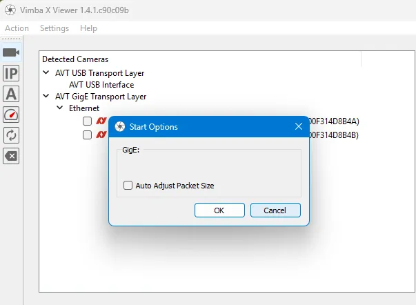
Disable automatic packet size adjustment in Vimba Viewer
Section titled “Disable automatic packet size adjustment in Vimba Viewer”Vimba Viewer has some default settings that should be disabled after installation. If they are left enabled, then opening Vimba Viewer will interfere with how Designer configures the cameras.
Please follow these steps to disable any interfering Vimba settings:
- In Vimba Viewer, go to Settings, then Start Options.
- Disable “Auto Adjust Packet Size” in the GigE section, see screenshot:
Verify camera communication
Section titled “Verify camera communication”- Open Vimba and select a camera.
- Press the play button and verify images are streaming.
In case camera connections are lost and regained (e.g. unplug/plug event), the Vimba Viewer software should detect them again automatically. In case they don’t, you can press the Refresh button in the top-left corner.
Configure cameras in Vimba
Section titled “Configure cameras in Vimba”You can right-click or double-click on the cameras to see and adjust the metadata of the camera.
This window also shows the Play button in the top left hand corner, on pressing this, the camera image should appear in this window, which can be zoomed using the mouse scroll button.
Focus, aperture, and focal length
Section titled “Focus, aperture, and focal length”It’s easiest to adjust position, orientation, focus, and aperture (iris) while looking at the live preview in Vimba Viewer. Position and orient the cameras so they look at the object that is to be projected onto. Ideally, the whole camera image should be taken up by the projected areas. It does not matter if the camera is mounted upside-down or right way up.
It is recommended to open the physical lens aperture (iris) as far as it can go (i.e. smallest F-Stop value). This will allow the most amount of light to enter the camera. You can then use the exposure time to control the total amount of light that hits the sensor for each frame. If the aperture is not fully open, then a longer exposure time is needed to achieve a similar overall brightness in the image. Any increased exposure time will also lead to slightly longer overall OmniCal capture times.
Adjust focus as needed by checking the image sharpness in Vimba Viewer. If the projected surface does not have many sharp visual features, then set up the projectors to output a suitable test pattern, so you can better assess the image sharpness. You may need to experiment with changing exposure time and focus settings, alternating between them, until you can clearly see a sharp image that is not too blown out (i.e. bright areas causing bloom/bleed in neighbouring camera pixels).
Note down the focal lengths used by each camera (they are written on the lens body); you will need these values later in Designer.
Brightness, Exposure Time, and other settings
Section titled “Brightness, Exposure Time, and other settings”Exposure time
Section titled “Exposure time”Exposure time will heavily depend on the light levels in the calibration environment and the aperture setting of the lens. On the right-hand side, you will see a value in milliseconds that allows you to calculate roughly the FPS the camera is producing. As mentioned above, longer exposure times will lead to lower FPS and thus slower OmniCal captures.
Other parameters do not need to be adjusted. Gain may need adjusting in exceptional circumstances, but in 99% of all cases, adjusting aperture and exposure time is enough.
The “All” tab allows you to type in a filter pattern and search through all settings. This is useful for changing the DeviceUserID (see also below). Just type in the settings name and click Search. The DeviceUserID will be visible inside Disguise and is used to map OmniCal Plan cameras to physical cameras.
Renaming cameras in Vimba Viewer
Section titled “Renaming cameras in Vimba Viewer”We recommended adding unique names for each camera for easier identification within Designer. Follow these steps to set this up:
- Close Designer.
- Open Vimba Viewer.
- Locate the setting “DeviceUserID” (not to be confused with a similar setting labelled “DeviceID”, which cannot be changed).
- Rename the camera as desired.
- Press Enter and close this window.
- Close Vimba Viewer when all cameras have been renamed and re-open Designer.
- You may need to update the OmniCal Plan settings with the new camera device names.
- Previous OmniCal captures may no longer be fully usable due to the camera name change.
Connect to cameras in Designer
Section titled “Connect to cameras in Designer”There is a separate program in the Disguise software called VimbaCamServer.exe which is used to discover and connect MV cameras on the network. VimbaCamServer will find cameras on any local network adaptor, just like Vimba Viewer. VimbaCamServer is a separate process that communicates with Designer via a TCP-based network protocol.
The Cameras collapsible widget contains network settings and camera lists for troubleshooting.
Camera discovery
Section titled “Camera discovery”The OmniCal Calibration editor configures and enables camera discovery on the network. Usually, VimbaCamServer is run locally on the Director server, so Designer can directly communicate with it. Set the Discovery Adaptor to the localhost “Loopback” adaptor, which is also the default. VimbaCamServer is launched automatically from within Disguise if this is set, and discovery is enabled. In this typical setup, the network switch with the cameras needs to be connected directly to a dedicated network adaptor on the Director server.
VimbaCamServer and Designer
Section titled “VimbaCamServer and Designer”The default “Loopback” adaptor essentially describes a local “network” connection between Designer and VimbaCamServer. The latter handles the actual camera GigEVision communication and captures images as PNG files for use in Designer. It communicates via the discovery adaptor with Designer, which in turn processes information and images within OmniCal. So the discovery adaptor is different to the adaptor that actually connects a machine to the camera switch.
Therefore, regarding network bandwidth, it’s the network adaptor to the camera switch that matters, not the Loopback adaptor (since that is basically only limited by the PCI bus).
The VimbaCamServer can also be run separately, e.g. on a stand-alone computer. In that case, the Discovery Adaptor inside Disguise needs to be selected as the network port with which the Disguise server machine is connected to this other computer. The Director server does not need a direct connection to the cameras or the network switch they are on. In other words, the discovery adaptor needs to be set to the network adaptor that the camera server app is on. The VimbaCamServer can be anywhere as long as it can see and connect to the cameras, and it can communicate with the Director.
Having VimbaCamServer on a different machine can reduce CPU load on the Director during OmniCal captures (it won’t have an impact when not capturing). However, this requires manual process management on the other machine, so it is not a recommended use-case.
Network ports used by OmniCal
Section titled “Network ports used by OmniCal”VimbaCamServer and Designer communicate with each other using different network protocols and ports:
- An OSC device
omnicaldiscoverythat broadcasts from the Director, to discover the VimbaCamServer process. These OSC broadcasts are sent every 30 frames, unless OmniCal capture is in progress.
By default, this OSC device uses port 9001, but this can be changed via the Device Manager.
Note that theomnicaldiscoveryOSC device is only visible in the current Device Manager while OmniCal camera discovery is enabled. - A proprietary TCP-based protocol to send image requests, etc., and reply with ACKs and actual image data.
This protocol uses ports 10101 and 10102 for sending from and receiving to the Director. These ports cannot currently be changed.
List of discovered cameras
Section titled “List of discovered cameras”The Discovered Cameras button opens a list of OmniCal cameras that have been discovered by Designer. The background colour for each camera row will indicate the state of the camera:
- Green: This means cameras are ok and receiving data from VimbaCamServer (with respect to the stats measuring incomplete frames between each receipt of stats).
- Red: This means there have been incomplete frames between the last read and the current read. The count of incomplete frames will continue to increase. The red colour will reset if there have been no incomplete frames between each read of the stats.
- Grey: This indicates the camera is disabled, e.g. due to incompatibility or licensing restrictions.
- Brown: This indicates the camera is disconnected / offline.
Camera statistics
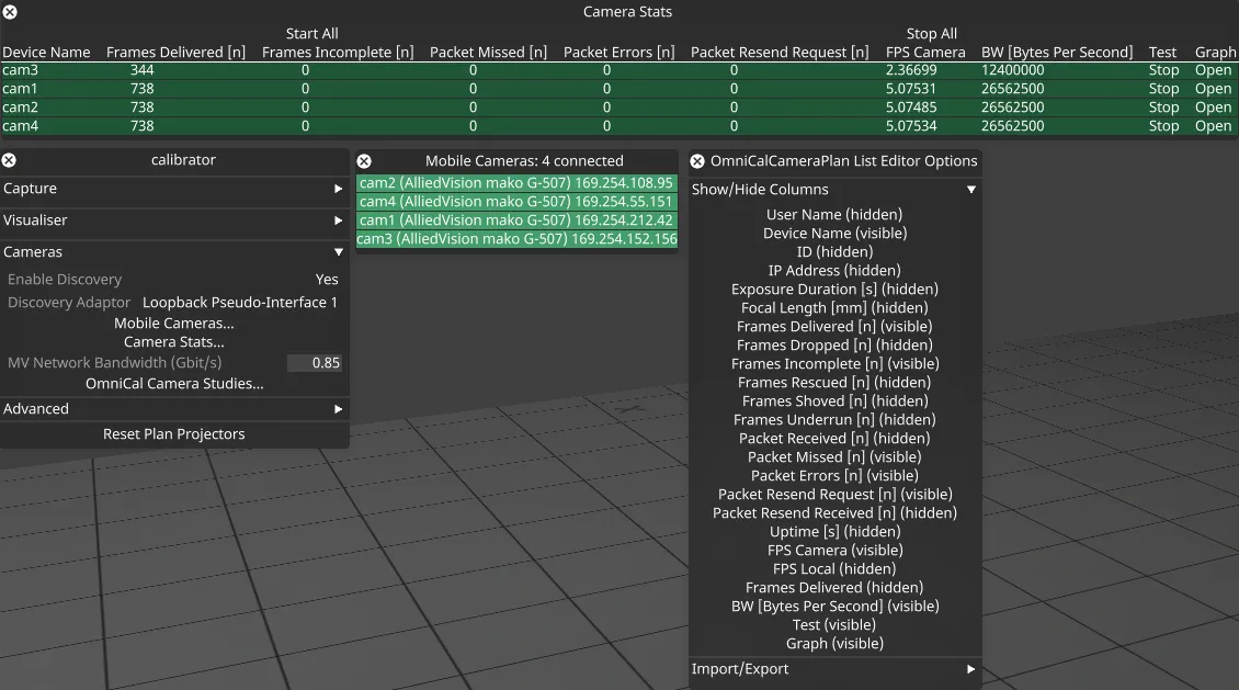
Section titled “Camera statistics”Plan Camera Stats overview
Section titled “Plan Camera Stats overview”The Plan Camera Stats button opens a window with a list of OmniCal cameras that are in the current Plan. It offers tools to test and troubleshoot cameras and the network by starting camera streaming without capturing images to disk. The window contains a table with rows for every camera, which collect various statistics like captured and dropped packets / frames or the camera temperature. Right-click the title bar to configure which kind of statistics should be shown in the table.
It is possible to test streaming for all cameras in the current Plan or only for a few selected cameras. This can help to identify whether an issue is specific to a certain camera or cable, etc.
A certain amount of dropped packets can be tolerated in a properly set up camera network, but dropping entire frames should be avoided. These stats can be used to evaluate the impact of changes to e.g. network settings or the usable bandwidth (see next section). Checking the impact on dropped packets/frames here is much quicker than trying out a full OmniCal capture, which might time out half-way through.
How to use Plan Camera Stats
Section titled “How to use Plan Camera Stats”- Make sure to assign the physical OmniCal cameras to the cameras in the OmniCal Plan.
If you see Plan Camera Stats greyed out, then you have not finished this step, or no physical cameras have been discovered. - The columns display various camera stats and feedback of camera properties (such as IP, name).
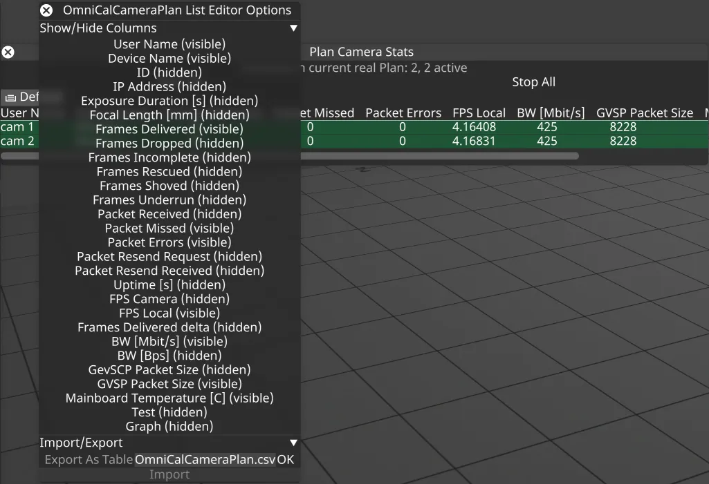
- Right-click the widget header to show available columns and enable or disable them:
- Click Start to enable streaming and stats feedback for a single camera. Click Stop to turn the stream off again.
- Click Start All to enable streaming and stats feedback for all cameras.
- The Open button in the Graph column opens a graph window that shows how the stats change over time.
- The Import/Export separator allows exporting the currently visible columns and their camera values to a CSV text file for troubleshooting analysis.
Plan Camera Stats columns
Section titled “Plan Camera Stats columns ”The values in each Plan Camera Stats table row will update while a camera is streaming. Starting to stream will reset the values for each camera that is streaming.
Some of the collected statistics are specific to GigEVision network protocols. This will be indicated with a “[GigE]” tag at the end of the description. For additional information about those stats, please visit the Allied Vision GigE features reference (chapter “Statistics”, page 163).
Meaning of camera statistics columns
Section titled “Meaning of camera statistics columns”User Name
Section titled “User Name”The user-specified name given to the associated camera in the OmniCal Plan.
Device Name
Section titled “Device Name”The user-specified name of the OmniCal camera, as set in Vimba Viewer.
The unique hardware ID of the OmniCal camera.
IP Address
Section titled “IP Address”The current IP address of the OmniCal camera.
Exposure Duration [s]
Section titled “Exposure Duration [s]”The exposure time in seconds. Smaller values can lead to faster capture, but also darker images.
Focal Length [mm]
Section titled “Focal Length [mm]”The camera lens focal length in millimetres, as set in the OmniCal Plan.
Frames Delivered
Section titled “Frames Delivered”The number of complete, error-free frames that were successfully delivered to the host. [GigE]
Frames Dropped
Section titled “Frames Dropped”The number of incomplete frames received by the host due to missing packets (excluding shoved frames). [GigE]
Frames Incomplete
Section titled “Frames Incomplete”Frames incomplete provides some feedback about the stability of the camera connections in VimbaCamServer. The value may be larger than Frames Dropped.
It measures how many video frames were not completed for any reason, e.g.:
- not all packets were received, despite resend attempts (packet loss)
- frame is now obsolete (see Frames Shoved)
- failed to validate the frame data
- exceptions when handling frame data from Vimba API
See Troubleshooting below for information on how to resolve incomplete frames and other network issues.
Frames Rescued
Section titled “Frames Rescued”The number of frames that initially had missing packets but were successfully completed after packet resend. [GigE]
Frames Shoved
Section titled “Frames Shoved”The number of frames dropped because the transfer of a following frame was completed earlier, making the previous frame obsolete. [GigE]
Frames Underrun
Section titled “Frames Underrun”The number of frames missed due to the non-availability of a user-supplied buffer. [GigE]
This means the Director was not ready to copy a completed frame from the camera. Values above zero may indicate issues with server system load, e.g. the CPU is busy with other work, or threading / priority issues. On machines with few CPU cores (e.g. 4) this may be resolved by adjusting advanced machine settings such as omniCalMaxThreadsPng.
Packet Received
Section titled “Packet Received”The number of error-free packets received by the driver. This number should grow steadily during continuous acquisition. [GigE]
Packet Missed
Section titled “Packet Missed”The number of packets missed due to network issues. [GigE]
If everything is configured correctly, this number should remain zero, or at least very low compared to the Packet Received value.
Packet Errors
Section titled “Packet Errors”The number of improperly formed packets. If this number is not zero, it suggests a possible cable or camera hardware failure. [GigE]
Packet Resend Request
Section titled “Packet Resend Request”The number of missing packets that were requested to be resent from the camera. [GigE]
If everything is configured correctly, this number should remain zero, or at least very low compared to the Packet Received value.
Packet Resend Received
Section titled “Packet Resend Received”The number of packets that were actually resent by the camera. [GigE]
Uptime [s]
Section titled “Uptime [s]”The elapsed time in seconds since the camera stream was started. [GigE]
FPS Camera
Section titled “FPS Camera”The rate at which the camera is acquiring frames, derived from the timestamps of completed frames. [GigE]
FPS Local
Section titled “FPS Local”Inverse of time interval between the last two frames (faulty or not) received by the host. No averaging is performed. [GigE]
In case of error-free reception, FPS Local is similar to FPS Camera, except that the host (system) clock is used instead of frame timestamps for measuring the time interval between frames. In case of errors, the two values may differ significantly, since FPS Local includes incomplete frames.
Frames Delivered Delta
Section titled “Frames Delivered Delta”Difference in Frames Delivered between the most recently received camera stats and the previous value.
BW [Mbit/s] 2
Section titled “BW [Mbit/s] 2”The network bandwidth in Megabits per second (Mbit/s) that is allocated to this camera. [GigE]
This is an even share of the total MV Network Bandwidth configured in Designer. Note that the total bandwidth is specified in Gigabits per second, not Megabits.
BW [Bps]
Section titled “BW [Bps]”The network bandwidth in bytes per second that is allocated to this camera. [GigE]
In GigEVision protocols this value is reported as StreamBytesPerSecond.
This is an even share of the total MV Network Bandwidth configured in Designer. Note that the total bandwidth is specified in Gigabits per second, not bytes.
GevSCP Packet Size 1
Section titled “GevSCP Packet Size 1”Packet size (MTU) in bytes for camera device (GigE Vision SCPS protocol). [GigE]
In a correctly set up system this value is the same as the Jumbo Packet setting configured for the network adaptor. If it is lower, then this indicates a problem elsewhere in the network signal chain. For example, a value of 1500 bytes indicates that Jumbo Packets are not enabled or supported across the whole signal chain. A value of around 4000 bytes may indicate a misconfiguration in a network switch. For more information, please refer to the Troubleshooting section.
GVSP Packet Size 1
Section titled “GVSP Packet Size 1”Packet size (MTU) in bytes for camera stream (GigE Vision Stream Protocol GVSP). [GigE]
This value should be identical to GevSCP Packet Size.
Mainboard Temperature [C] 1
Section titled “Mainboard Temperature [C] 1”Temperature of the camera main board in degrees Celsius. Accuracy: +/- 1 °C [GigE]
Camera Bandwidth
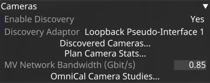
Section titled “Camera Bandwidth”The field MV Network Bandwidth (Gbit/s) configures the total amount of usable bandwidth for OmniCal MV cameras. The network needs to reliably provide this bandwidth. Typically, this should be set to a value about 80-90% of the theoretical bandwidth of the link between the camera switch and the server running VimbaCamServer (e.g. the Director). The default value is 0.85 Gbit/s, which should work for most 1G network setups. On a true 10G link to the Director a value of up to 8.5 Gbit/s should work.
If the network cannot reliably provide this usable bandwidth (e.g. due to traffic or interference from other devices), it will lead to dropped packets and potentially disconnected cameras.
In this case it may help to reduce the MV Network Bandwidth value. Reducing the total bandwidth value will further slow down the capture, but allow for more room for packet re-sends, to avoid dropped frames. The appropriate bandwidth value depends on the quality of the network setup and the nature of any interference.
OmniCal camera specs and bandwidth
Section titled “OmniCal camera specs and bandwidth”OmniCal MV cameras have a 5.1 MegaPixel image sensor with 2464x2056 pixels and capture 8-bit monochrome images. The size of a single image is 5065984 bytes, and the respective bandwidth would be 40.5 MBit/s. At their maximum framerate of 23 FPS, a single camera would require 932.1 MBit/s bandwidth, which is roughly above the effective capacity of a 1G Ethernet connection.
In OmniCal, the typical frame rate of each camera is much lower than 23 FPS, partly because they are mostly used in dark environments, where longer exposure times are needed. Exposure times have a direct effect on the maximum frame rate that can be used. Assuming a frame rate of e.g. 10 FPS, a single camera would need a bandwidth of about 405 MBit/s, which is almost half of the effective bandwidth of a 1G Ethernet connection.
Since OmniCal is typically used with more than 2 cameras, Designer needs to carefully manage the usable bandwidth of every camera, so the total camera bandwidth does not exceed the available bandwidth of the network connection. Note that this also has a further impact on the maximum frame rate that can be achieved: more cameras means a lower maximum framerate (assuming network bandwidth stays the same).
Bandwidth management in Designer
Section titled “Bandwidth management in Designer”Every time an OmniCal capture is started, Designer (or rather its sub-process VimbaCamServer) sets the bandwidth for each camera explicitly. Every camera gets an equal share of the total bandwidth set in Designer. For example, when using 4 cameras and 0.8 Gbit/s, every camera will be configured to use 0.2 Gbit/s.
This will overwrite any bandwidth setting configured externally, e.g. in Vimba Viewer.
The bandwidth also has an impact on the practical FPS and capture speed for each camera. The more cameras are connected, the longer each camera will need to stream a whole frame. Therefore, with equal bandwidth, more cameras result in reduced maximum FPS and longer capture time.
Bandwidth management in Vimba Viewer
Section titled “Bandwidth management in Vimba Viewer”Any automatic bandwidth or packet size adjustment in Vimba Viewer should be disabled, because it will interfere with how Designer configures the cameras.
Troubleshooting
Section titled “Troubleshooting”Always verify first that all network settings are as required for switches and network adaptors.
Camera has red lock icon in Vimba Viewer
Section titled “Camera has red lock icon in Vimba Viewer”This indicates that the camera is already opened elsewhere, for example, another laptop running Vimba Viewer or Disguise Designer.
Camera access is exclusive; if you have a camera opened for capture in Designer, you will not be able to view it in Vimba and vice versa.
No image is displayed in Vimba Viewer
Section titled “No image is displayed in Vimba Viewer”On older servers, it may be worth trying to disable Jumbo Frames on the network adaptor that connects to the camera switch, or at least configuring them to a lower size. This has been observed in the past with legacy 4x4 pro servers, where Jumbo Frames with an MTU size over 2034 bytes was unable to get complete images from the cameras, due to packet loss. An alternative workaround would be to limit the packet size on the switch.
Use Vimba Viewer to verify the GVSP packet size setting is 2034 or below. This value is not set directly, but negotiated automatically between network adaptor, switch and cameras.
Network adaptor gets disabled in Windows after applying suggested settings
Section titled “Network adaptor gets disabled in Windows after applying suggested settings”Try reverting the Interrupt Moderation Rate to the default value, which is Adaptive on most Intel adaptors. It may be necessary to re-enable the adaptor manually in Windows Advanced Network Settings.
Cameras drop out shortly after capture starts
Section titled “Cameras drop out shortly after capture starts”If cameras work individually in Vimba Viewer but not when capturing multiple cameras with OmniCal, this could indicate an incorrect multicast configuration. Check whether multicast is enabled on the switch and either disable it or ensure IGMP Snooping is enabled. For more information, see the sections on multicast and switch setup.
If this does not help, please follow the steps below.
Very slow image capture, dropped packets, incomplete frames, or cameras become unresponsive
Section titled “Very slow image capture, dropped packets, incomplete frames, or cameras become unresponsive”- Ensure that Vimba Viewer does not overwrite the packet size set by Designer, see instructions here.
- Verify that the cameras are communicating using Jumbo Frames.
- The reported GVSP packet size in Vimba Viewer should match the values you set for the network adaptor and switch (e.g. 9000 bytes).
- You can also check the GVSP value in the
console_vimbacamserver.txtlog file. - A value of 1500 indicates that Jumbo Frames were not enabled somewhere in the signal chain. Please check and adjust network switch settings, including for individual ports.
- Any value between 1500 and 8000 indicates that some networking equipment in the signal chain is configured for smaller Jumbo Frames than desired (e.g. 4082). Please check and adjust network switch settings, including for individual ports. If this cannot be addressed, it may be necessary to reduce the total usable bandwidth in Disguise Designer (see Camera Bandwidth).
- Any network switch that does not support Jumbo Frames must be removed from the signal chain.
- Use the Plan Camera Stats window to get more information about the network behaviour.
- Test whether any network issues are specific to a certain camera or cable by streaming them individually.
- If issues like dropped packets only occur with a certain camera, then try swapping cables and check other network equipment in that camera’s signal path.
- Add more cameras one-by-one to test whether problems only start after using a certain number of cameras.
- If this is the case, it may be necessary to reduce the total usable bandwidth in Disguise Designer (see Camera Bandwidth).
- Reducing the bandwidth will lead to slower image capture. But in a congested network this may still improve the capture performance, as it will lead to fewer dropped packets that then don’t need to be re-sent.
- Test whether any network issues are specific to a certain camera or cable by streaming them individually.
- Ensure that the camera network is clean from any other interference.
- Verify that OSC devices in Designer (including the
omnicaldiscoveryOSC device) do not clash on their port numbers. See Network ports used by OmniCal for more information. - Verify that the camera network is physically separate, with no other devices on it.
- Use Wireshark to monitor network traffic on the OmniCal network adaptor to spot any devices sending packets on this network. Devices such as lighting desks might flood the network with messages, or other machines might incorrectly use this network for copying data.
- Verify that OSC devices in Designer (including the
- As mentioned in Network setup, VLANs and adaptor virtualisation are not officially supported, as they make it very difficult to guarantee the required bandwidth for the OmniCal cameras.
- If a dedicated physical network is not available, then packets will be dropped whenever there is other traffic, which can lead to camera timeouts during capture.
- The likelihood of this happening can be reduced by reducing the total usable bandwidth in Disguise Designer (see Camera Bandwidth).
- Try reverting the Interrupt Moderation Rate to the default value, which is Adaptive on most Intel adaptors.
- This usually helps in situations where the MTU / packet size is smaller than the recommended value of 8-9 kbytes (see Interrupt Moderation Rate and Jumbo Frames / Packets).
- Try changing the Flow Control setting from Enabled to Disabled, or vice versa (see Flow Control).
Restarting unresponsive cameras
Section titled “Restarting unresponsive cameras”The easiest way to restart a camera is to disconnect and reconnect it from the PoE switch. For managed switches, this can usually be done without physically touching the cables, via a configuration GUI (e.g. browser interface) or even API commands.
Further Reading
Section titled “Further Reading”GigE Vision (R) industry standard
Allied Vision GigE installation manual
Allied Vision GigE features reference
GeniCam Network Card Performance Settings
Advanced Driver Settings for Intel® Ethernet 10 Gigabit Server adaptors