OmniCal Capture
Capture is the process of projecting structured light patterns, taking images of these and detecting blobs within these images.
After completing camera and network setup, OmniCal is ready to capture using the Plan workflow:
- Configure the positions and properties of cameras and projectors.
- Setup the Capture.
This may require adjusting exposure, projection and alert settings. - Perform the Capture and wait for completion.
The capture may take a while to complete. OmniCal will show the progress in the UI and may alert users of issues that require their attention.
OmniCal Stage Plan
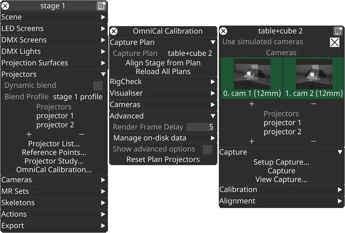
In the Stage editor, under Projectors, click OmniCal Calibration to open the Calibration editor. This widget controls the main OmniCal behaviour. Right-click on any Capture Plan to open its OmniCalStagePlan editor.
In the OmniCalStagePlan we recommend working through the sections from top to bottom: Capture, Calibration, Alignment, and Mesh Deform (if required).
Plan Workflow
Section titled “Plan Workflow”This page details the OmniCal Plan workflow intended for trained users. For re-calibration of existing Plans, please see the RigCheck workflow.
Configure cameras and projectors
Section titled “Configure cameras and projectors”- Left-click the calibration editor from the stage editor to open it.
- To create a new Capture Plan, left-click on CapturePlan.
This opens the capture plan manager. - Enter a name in the New OmniCalStagePlan field and click OK.
- Right-click the newly created capture plan.
- To work with simulated capture (without physical cameras), enable Use simulated cameras.
- Click the + icon to add a new plan camera to the plan.
- Right-click on each of the plan cameras to open its camera plan editor, to make further changes:
- Adjust camera settings like offset, rotation or focal length as needed.
The pose will be used for visualisation, and also for simulated captures. - If physical cameras are connected, then click Physical OmniCal Camera and select the appropriate camera from the list of discovered cameras.
- Ensure that the configured focal length matches the physical lens.
- Adjust camera settings like offset, rotation or focal length as needed.
- Click the + icon to add projectors to the plan.
- Ensure that projector outputs are correctly assigned in the Feed View.
- Ensure that projection surfaces are correctly assigned to the projectors.
Capture Setup
Section titled “Capture Setup”When using physical cameras (no simulation), Capture Setup requires the camera network to be set up correctly (see previous chapter OmniCal Setup.
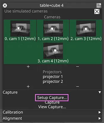
- Left-click Setup Capture to open the Capture Setup window.
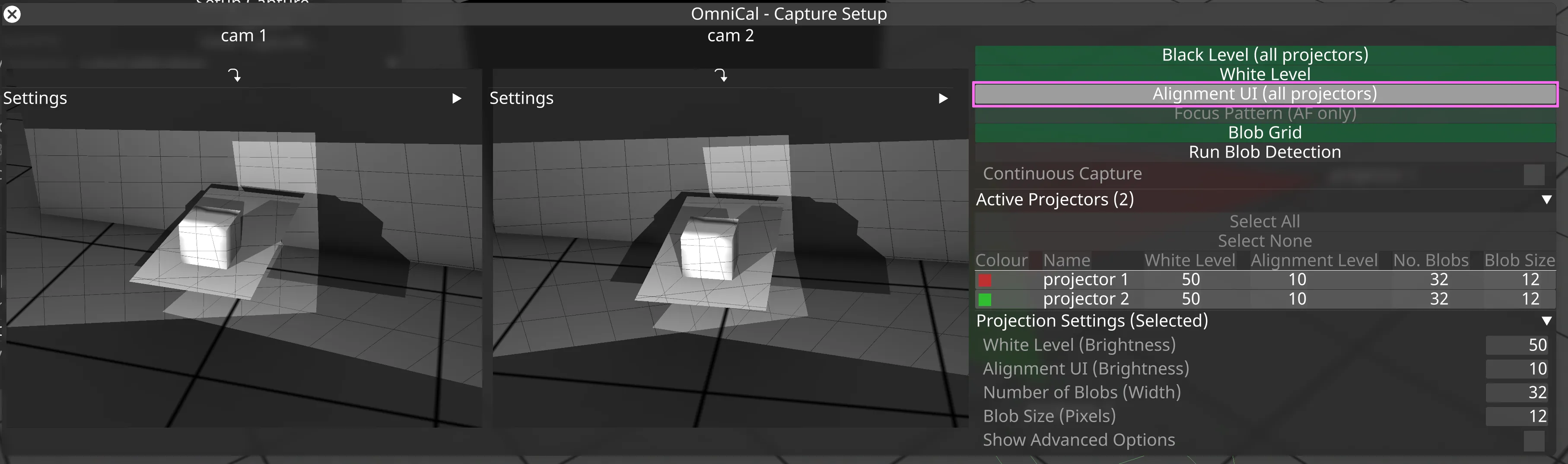
- Click Black Level (all projectors) to capture the OmniCal camera view when projectors are outputting black. Black Level images should be fairly dark, but still allow recognition of important scene elements. Adjust using lens aperture (iris) on the physical lens and exposure time in Designer. Only use gain if the desired look cannot be achieved with other means.

- Click White Level and adjust the White Level (Brightness) value to make sure the camera images are not overexposed. Click on any projector to view and adjust it individually. The goal is to achieve a similar brightness for all projectors in the camera images.

- Click Alignment UI (all projectors) and adjust the Alignment (Brightness) value to make sure you can clearly see the grid on the projection surface. The goal is to have alignment images where you are able to visually identify parts of the real-world projection surface, so they can later be matched up in QuickAlign (after Capture and Calibration).
- Click Blob Grid to see how many blobs are projected, and how well they cover the surfaces you are calibrating.
Then adjust the blob size and the grid size (Number of Blobs) according to your projector and camera setup.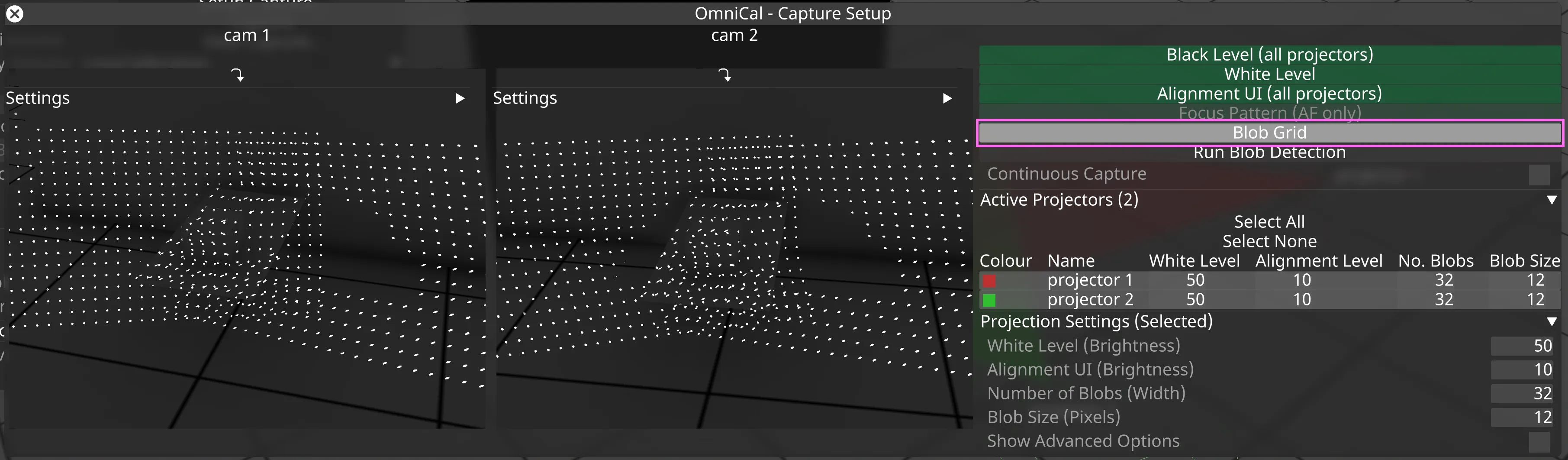
- The blob size is the size of projected blobs in pixels (in each projector’s output image). This should be chosen as small as possible, but so that blobs are still clearly visible in all camera images. Note that the same blob may appear smaller in cameras that are further away or use wider-angled lenses (smaller focal length).
- The grid size is the number of blobs projected horizontally. Note that high values for grid size and larger blob sizes may lead to blobs touching each other. This must be avoided. Blob detection will fail if there is no clear gap between individual blobs.
- Blobs should appear with enough contrast against the background (i.e. Black Level) to make them easy to recognise.
- Click Run Blob Detection to test the blob detection on all OmniCal cameras.
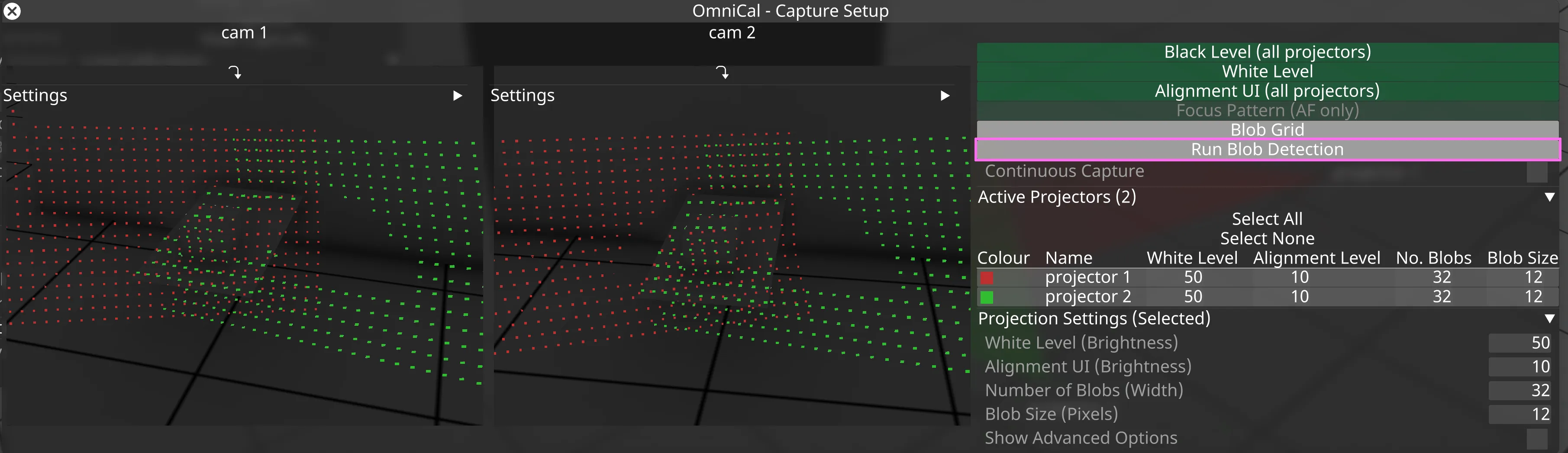
- A test blob detection will take a few moments until all cameras have taken images for all projectors. Results will be highlighted in each camera view.
- Detected blobs will be shown in the respective projector colour.
- At this stage the camera aperture or exposure may need adjusting, to improve blob detection and make it consistent for all cameras.
- To adjust exposure, click on the camera name and adjust the exposure time in the Camera Plan Editor.
- Adjusting the camera lens aperture requires physical access to the focus ring on the physical camera lens.
Configure OmniCal Alerts
Section titled “Configure OmniCal Alerts”Alert settings allow users to adjust how OmniCal behaves when it encounters potential issues, such as blurry camera images. If a configured threshold is crossed, OmniCal will alert the user via a notification.
At the moment, alert settings only affect OmniCal post-capture processes that run towards the end of a capture. Some settings apply to both the Plan and RigCheck workflow, and some only to RigCheck.
These alert settings are user-configurable, to allow adjusting to specific project or environmental demands.
OmniCal alert settings typically consist of absolute or relative thresholds (percentages) that the current capture is compared against:
- Absolute thresholds are compared directly against actual values calculated during the capture. Depending on the process, a notification is either triggered if the current value is greater or smaller than the threshold.
- Relative thresholds are used to compare an absolute value from the current (RigCheck) capture against the equivalent value from the earlier Plan capture. A deviation greater than the configured percentage will trigger a notification.
Settings for camera focus detection
Section titled “Settings for camera focus detection”Camera focus detection checks captured images whether they are out-of-focus (i.e. blurry) by calculating a blur score for each camera.
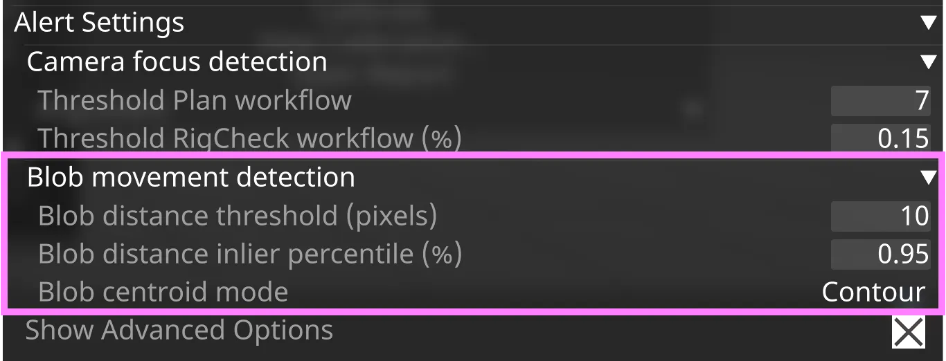
Threshold Plan workflow
Section titled “Threshold Plan workflow”Absolute threshold for blur scores. Detects if the camera lens is potentially out of focus. Smaller values mean “less in focus” or more blurry.
- Unit: unitless
- Range: 0 - 1000. Default: 7
- Threshold type: absolute
- Workflow: Plan and RigCheck
Threshold RigCheck workflow (%)
Section titled “Threshold RigCheck workflow (%)”Relative threshold for comparing blur scores between RigCheck and the original Plan. Detects if the camera lens focus has deteriorated since the initial installation.
- Unit: percentage
- Range: 0 - 1. Default: 0.15
- Threshold type: relative
- Workflow: RigCheck

Settings for blob movement detection
Section titled “Settings for blob movement detection”Blob movement detection checks whether captured blob coordinates have moved between the original Plan and a subsequent RigCheck. If the measured movement exceeds the defined limits, then OmniCal generates a notification.
Blob movement detection only applies to the RigCheck workflow.
Blob distance threshold (pixels)
Section titled “Blob distance threshold (pixels)”Absolute threshold for average blob movement when comparing blob coordinates of the current RigCheck to the original Plan. OmniCal will show a notification if the calculated value is above this threshold.
- Unit: pixels
- Range: 0 - 200. Default: 10
- Threshold type: absolute
Blob distance inlier percentile (%)
Section titled “Blob distance inlier percentile (%)”Which percentile of blob centroid distances to use for calculations (assuming a normal distribution of the distances). Values outside the specified percentile are ignored for the blob movement calculation. Setting this below 100% helps to prevent the effect of outliers distorting the average distance result.
Default: 0.95, i.e. 95%.
Blob centroid mode
Section titled “Blob centroid mode”Determines which blob centre coordinate to use for calculations: Contour, Ellipse, BoundingBox, or BrightestPoint. This is an advanced setting that normally does not need to be adjusted.
For each blob, OmniCal stores 4 different centre coordinates. These centre values may vary depending on the shape of the blob (as it appears in the camera). For example, a projected circle may only be partially visible in a camera, leading to a deviation between the centres of, e.g. the detected contour and an ellipse modelled around it.
Default: Contour.
Perform a capture
Section titled “Perform a capture”Capture preparation to avoid interference
Section titled “Capture preparation to avoid interference”During an ongoing capture, we recommend the following:
- The stage should be clear of interfering objects that might obscure the projection surface (e.g. ladders or other construction equipment).
- No changing light levels.
- No reflective surfaces in the projection path.
- No moving projection surfaces.
- No people walking across the projections or camera views.
Any such interference may lead to incorrect capture data that causes bad calibration results. If you notice any such interference or other capture problems, then cancel the current capture, remove the source of the problem and start a new Capture.
To perform a capture
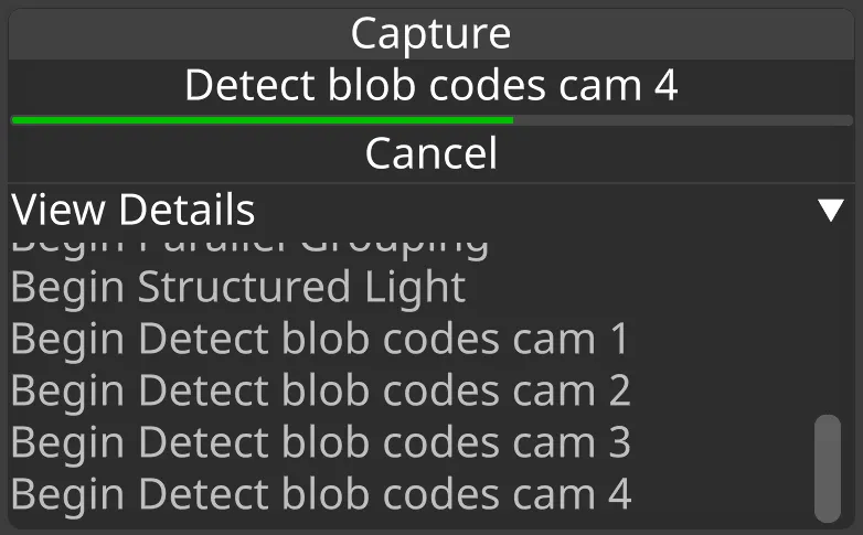
Section titled “To perform a capture”- Click Capture from the plan editor.
- The system will perform a capture.
- The time taken depends on the number of projectors and cameras, whether projectors are converging or not and any overlap between projectors. For example, 4 cameras and 4 non-converging projectors takes roughly a minute.
- OmniCal will run some post-capture processes towards the end of the capture. These processes compare images against configurable thresholds, and may produce notifications if any thresholds are triggered.

- The time taken depends on the number of projectors and cameras, whether projectors are converging or not and any overlap between projectors. For example, 4 cameras and 4 non-converging projectors takes roughly a minute.
- Verify the results of the capture by clicking View Capture.
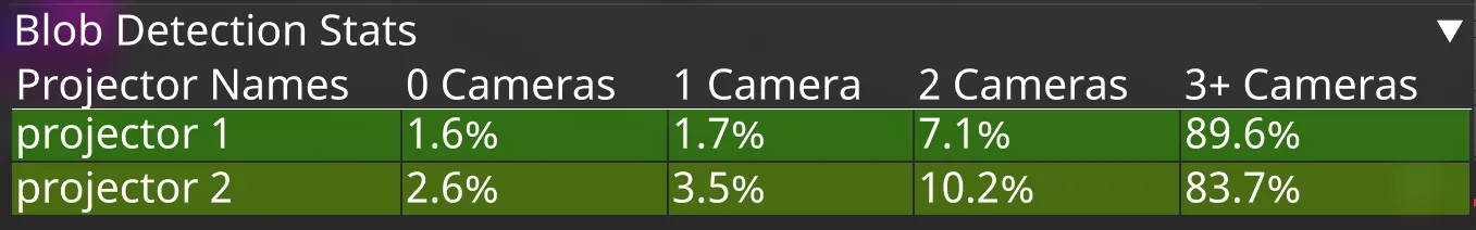
- Click Blob Detection Results to see which blobs were detected in the cameras.
- Verify that the blob detection results are as expected. These results should be consistent with what you saw earlier in the capture setup.
- Blob statistics show how many cameras observe / detect a projector’s blobs. An observer ratio of 50% or higher would be ideal.
Post-capture processes
Section titled “Post-capture processes”During the OmniCal capture, certain post-capture processes will automatically run on some of the captured images. The purpose of these processes is to detect whether any conditions outside of Designer may affect the quality and validity of the capture.
Images are compared against configurable thresholds, and if any thresholds are triggered, OmniCal will notify the operator with relevant information and suggestions for next steps.
Camera focus detection
Section titled “Camera focus detection”Camera focus detection helps to ensure that all OmniCal camera lenses are in focus. If a camera is found to potentially be out of focus, a notification will be issued. Operators may then need to manually adjust the lens focus on the physical camera.
Camera focus detection uses Fourier Transform algorithms to calculate a blur score for each camera. This score is compared to thresholds to detect whether the image is likely blurry.
Users can configure the behaviour of this process using threshold settings. The thresholds may also get automatically adjusted by OmniCal, based on the nature of the scene (see below). If the blur score for a camera is below the adjusted threshold, then this camera’s lens is likely out of focus.
Meaning of calculated blur score
Section titled “Meaning of calculated blur score”The blur score is a unitless measure that determines how relatively in or out of focus a camera lens is. A higher blur score means a more focused, and a lower score describes a more blurry image.
Note that the blur score also depends on the mage content, and can vary for a given camera, even if the lens focus is not modified. This is because the blur score calculation is sensitive to scene composition and environmental influences, including:
- Light distribution in the scene
- Very dark (underexposed) or very bright (overexposed) areas are equivalent to low frequencies, so will lead to worse blur scores.
- Natural structure of the scene
- Uniform colour / structure areas are equivalent to low frequencies, so will lead to worse blur scores.
If a captured image was found to have any of the above influences, then the configured threshold will be automatically adjusted accordingly, to prevent false positive warnings.
Blob movement detection
Section titled “Blob movement detection”Blob movement detection helps to confirm that the scene and rig setup, camera alignment, and overall positioning remain consistent during the RigCheck workflow.
This process checks whether any of the projected blobs have shifted or moved in any camera images between the original Plan and a subsequent RigCheck. It identifies blob centres in both datasets, measures the distance between matching centres, and calculates the overall average movement in pixels.
Blob movement detection also detects if a camera can no longer “see” blobs from a certain projector. This may indicate that a projector is turned off, or its footprint has changed considerably.
Users can configure the behaviour of this process using threshold settings. If the measured movement exceeds any of the defined limits, then OmniCal generates a notification.
Meaning of detected Blob movement
Section titled “Meaning of detected Blob movement”If blob movement detection triggers a notification, then this can mean one (or more) of the following:
- One or more cameras have moved.
- The RigCheck will need alignment adjustment for each affected camera.
- One or more projection surfaces have moved.
- The RigCheck will need alignment adjustment for each affected surface.
- One or more projectors have moved.
- OmniCal will automatically update all projector calibrations.
- As long as the projection surface is still covered sufficiently, no further action is required.
- In case 2D warps or manual blend masks are used, these will likely need adjusting.
OmniCal cannot currently determine which of these situations has occurred. Operators are advised to visually check the scene for alignment issues and adjust them using the Result Aligner, if needed.
Managing OmniCal data on disk
Section titled “Managing OmniCal data on disk”OmniCal Plan data on disk
Section titled “OmniCal Plan data on disk”OmniCal’s Plan workflow stores a mix of data on the hard disk, rather than in the .d3 project itself.
This includes:
- OmniCal settings
- Captured images
- Calculated blob detection results
- Calibration results
- Alignment data
- Report data
This data is stored in subfolders of the Designer project’s internal/opticalstageplan/ folder.
Every Plan has its own set of data, and its subfolder has the same name as the associated Plan object in Designer.
The data in the internal subfolders is managed together with the corresponding Plan object in Designer: When the Plan object is deleted, and the trash in Designer is cleared, any associated folder (including images, config and result files) is also deleted from the hard disk.
Storing many Plans in a project folder can fill up the hard disk over time. It is usually a good idea to delete any Plans that are no longer in use. This not only frees up disk space; it also reduces confusion if there are many different Plans with similar names.
OmniCal RigCheck data on disk
Section titled “OmniCal RigCheck data on disk”RigCheck result data is treated the same as Plan data, except that it is stored in the Designer project subfolder internal/opticalresult/.
At the beginning of a RigCheck, all settings (including alignment data) are copied from the Plan to the new RigCheck result.
See also Managing RigCheck data on disk.
Comparing Plan variations
Section titled “Comparing Plan variations”Often it is necessary to compare the impact of different Plan setups or settings, e.g. the number of cameras or their placement or lens options. Sometimes it’s only the impact of calibration settings that needs to be compared.
This is best achieved by copying the relevant Plan and editing the copy:
- Right-click on the Plan title bar, choose a new name and click Duplicate.
- Make any required changes to the copied Plan’s settings.
- Start a new Capture and/or Calibration for the new Plan.
That way it’s possible to switch between the two plans without losing any previous settings or results. This is more flexible and will improve understanding of the impact of any changes to a Plan setup or its settings.