Fisheye Mapping
フィッシュアイマッピングは、フィッシュアイ投影を使ってコンテンツをスクリーンに投影し、半球レンズの効果をシミュレートします。このマッピングタイプは、ドーム、曲面、または中心点から放射状にコンテンツを分配する必要があるあらゆるシナリオに最適です。
フィッシュアイマッピングは、割り当てられたすべてのスクリーンを 1 つの統一されたキャンバスとして扱い、1 枚のフィッシュアイ歪曲画像をすべての面に投影します。これにより、ピクセル密度やスクリーン間隔を手動で計算する必要がなくなります。Designer は、面が移動したり向きが変わったりしても、正しいサンプリングと整合を自動的に処理します。
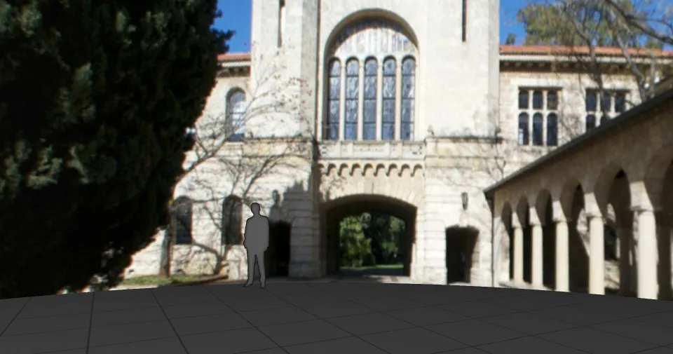
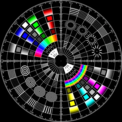
フィッシュアイコンテンツの例:
フィッシュアイマッピングの作成
Section titled “フィッシュアイマッピングの作成”- トラックに新しいビジュアルレイヤー(コンテンツ、ジェネレーティブ、またはエフェクト)を作成します。
- レイヤーを選択して Layer Editor を開きます。
- Default タブで Mapping パラメーターをクリックすると、利用できるマッピングが表示されます。
- mappings マネージャーで新しいマッピングを作成し、タイプとして Fisheye を選択します。
- 新しいフィッシュアイマッピングのエディターが表示されます。
- 使用するすべてのスクリーンを割り当て、目的のコンテンツ解像度を入力します。
- レイヤーにコンテンツを割り当てます。コンテンツは、ステージとフィード出力で、割り当てられたスクリーンにフィッシュアイマッピングされて表示されます。
- 必要に応じて、フィッシュアイマッピングの固有のプロパティを調整します。
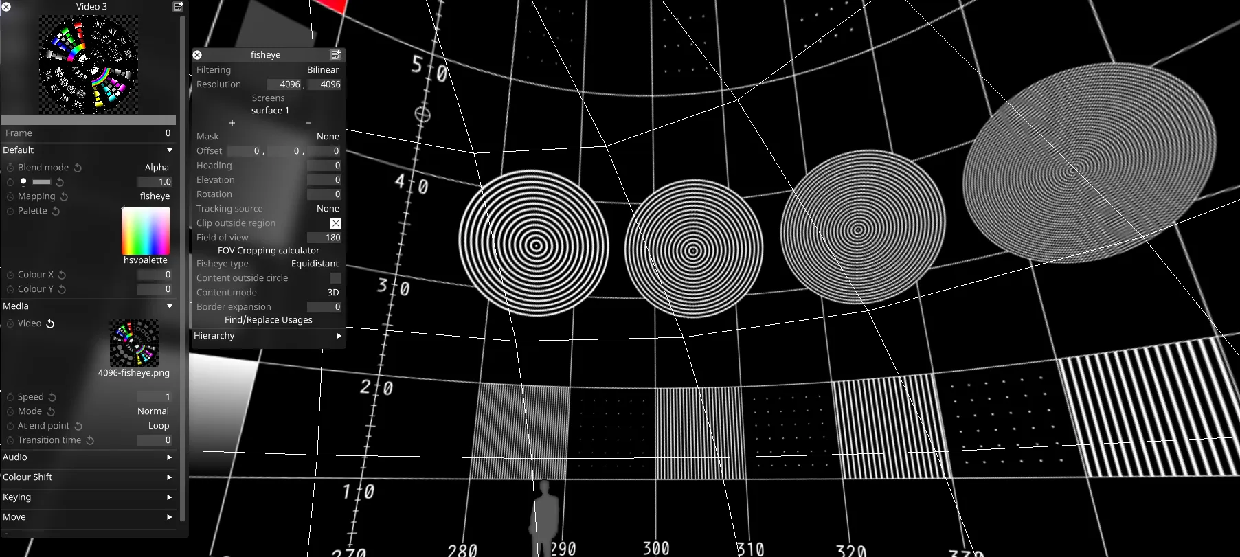
フィッシュアイマッピングエディターを開くと、Designer はマッピングされた領域の外側のエリアをハイライト表示し、投影パラメーターとクロッピングのコントロールを提供します。
マッピングプロパティ
Section titled “マッピングプロパティ”
Filtering(フィルタリング)
Section titled “Filtering(フィルタリング)”-
Nearest: 最近傍フィルタリング。最近傍サンプリングを使用し、スケーリング時のピクセル間のブレンドを無効にします。ピクセル化された見た目を作成したり、特定の種類のコンテンツでハードエッジを確保したりするために使用できます。
-
Bilinear: バイリニアフィルタリングは、実際のサイズより大きく、または小さく表示する際にテクスチャを滑らかにするために使用されるテクスチャフィルタリング手法です。
-
2x Multi-sample: マルチサンプルフィルタリングは、スケーリングされたコンテンツの問題を修正するのに役立ちますが、多少のぼかしが生じることがあります。
Resolution(解像度)
Section titled “Resolution(解像度)”これは、レイヤーがレンダリングするキャンバスのサイズをピクセル単位で制御します。ダイレクトマッピングタイプは 256x256 ピクセルのキャンバスから始まり、最初に追加したスクリーンのサイズに合わせてキャンバスサイズを自動的に設定します。
Screens(スクリーン)
Section titled “Screens(スクリーン)”選択したマッピングタイプがコンテンツをコピーできるスクリーンの一覧です。
- + を左クリックして Screens マネージャーを開きます。
- + を左クリックして、マッピングしたいスクリーンを追加します。これにより、個々のキャンバスコンテンツがこれら 3 つのスクリーンへ同時にコピーされ、マッピングオブジェクトエディターにスクリーン名が追加されます。
- マッピングオブジェクトエディターに一覧表示されたスクリーンを左クリックして - へドラッグします。これにより、スクリーンからキャンバスコンテンツが削除され、マッピングオブジェクトエディターからスクリーン名が削除されます。
Mask(マスク)
Section titled “Mask(マスク)”これは、Mask ビットマップを定義する Texture ファイルを指します。このプロパティを使って、マッピングキャンバスに Mask ビットマップを適用できます。このプロパティを選択すると Texture オブジェクトライブラリが開き、ローカルハードドライブの DxTexture フォルダーに保存されているすべての静止画像ファイルが表示されます。
マッピングマスクを適用するには、カスタムの静止画像ファイルを作成してインポートする必要があります。
-
カスタム Population マスクの作成とインポートの手順は、カスタムマッピングマスクの作成にも使用できます。唯一の違いは、マッピングマスクの解像度をマッピングキャンバスと同じにする必要がある点です。Population マスクを d3 プロジェクトに作成してインポートする手順については、[スクリーンの編集] (../content/docs/ja/designer/stage-setup/screens/screen-editor) のサブチャプターの「Population mask」のセクションを参照してください。
-
あるいは、任意のレイヤーのブレンドモードを mask に設定して、レイヤーのコンテンツをマッピングマスクへ流し込むこともできます。
Offset(オフセット)
Section titled “Offset(オフセット)”フィッシュアイ投影のアンカーポイントの位置をステージ空間(メートル単位)で設定します。マッピングが 階層 内にある場合は、親オブジェクトを基準とした相対値になります。
Heading(ヘディング)
Section titled “Heading(ヘディング)”フィッシュアイ投影を水平方向に回転させます(度数)。
Elevation(エレベーション)
Section titled “Elevation(エレベーション)”投影を垂直方向に傾けます(度数)。
Rotation(回転)
Section titled “Rotation(回転)”フィッシュアイ投影内でコンテンツを回転させます(度数)。
Tracking source(トラッキングソース)
Section titled “Tracking source(トラッキングソース)”マッピングをトラッキング対象のオブジェクトに アタッチ します。
Clip outside region(領域外のクリップ)
Section titled “Clip outside region(領域外のクリップ)”レンダリングされた領域の外側のピクセルをクリップし、既存の色を保持します。設定しない場合、レンダリングされた領域の外側のピクセルは境界色に設定されます。
Field of view & cropping calculator(視野とクロッピング計算機)
Section titled “Field of view & cropping calculator(視野とクロッピング計算機)”フィッシュアイ投影の角度範囲を設定します(度数)。FOV を大きくするとより広い領域を捉えられ、フルスフィアコンテンツの場合は 360° まで拡張できます。FOV を小さくするとマッピングがより狭い領域に集中し、ファイルサイズの削減に使用できます。デフォルト値は 180° です。
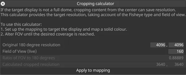
クロッピング計算機は、FOV とマッピング解像度との関係を調整するのに役立ちます。FOV をリアルタイムで制御し、その結果得られる解像度を元のマッピング解像度の係数として計算します。これにより、目的の表示領域に対してコンテンツが正しくサンプリングされるようにします。
なお、投影アルゴリズムによって FOV ごとのサンプリング挙動が異なるため、フィッシュアイタイプ(下記)も解像度の計算に影響します。
Fisheye type(フィッシュアイタイプ)
Section titled “Fisheye type(フィッシュアイタイプ)”フィッシュアイ投影のアルゴリズムを選択します。各タイプは解像度の分布に関して異なる特性を持ちます。
- Equidistant: 角度を半径に線形にマッピングし、FOV 全体にバランスの取れた解像度分布を提供します。一般的なフィッシュアイ用途でよく選ばれます。
- Equisolid: 面積の関係を保持するため、プラネタリウム投影など、等面積表現が重要な用途に適しています。
- Orthographic: 点を平面に投影し、エッジに向かってより圧縮された画像になります。芸術的な効果や特定の表示要件に役立ちます。
- Stereographic: 角度を保持するため、FOV のエッジ付近でオブジェクトの見かけのサイズが大きくなります。
Content outside circle(円の外側のコンテンツ)
Section titled “Content outside circle(円の外側のコンテンツ)”無効にすると、円形のフィッシュアイ領域の外側のコンテンツがクリップされます。有効にすると、矩形のマッピング領域全体が使用されます。これは、特定の FOV の外側にあるのがスクリーンのごく一部のみである場合に役立ち、通常は無駄になる領域をコンテンツで埋められます。
Content mode(コンテンツモード)
Section titled “Content mode(コンテンツモード)”2D または 3D のコンテンツマッピングを選択します。3D モードでは、レンズがカメラに変換されて 3D エンジンに送られ、本物の 3D パースペクティブと視差効果が可能になります。2D モードでは、コンテンツは常にフラットな画像として扱われ、カメラ情報はありません。
Border Expansion(境界の拡張)
Section titled “Border Expansion(境界の拡張)”スクリーン上の UV アイランドをこのピクセル数だけ拡張し、黒いフリンジなどのエッジサンプリングアーティファクトを覆います。これを活用するには、スクリーンの UV マップに同等の空きスペースが必要である点に注意してください。
Find/Replace Usages(使用箇所の検索/置換)
Section titled “Find/Replace Usages(使用箇所の検索/置換)”プロジェクト内で現在のマッピングが使用されているすべての箇所を検索し、それらを別のマッピングに置き換えられるようにします。置換は、シーケンス化された、Sockpuppet 化されていないマッピングに対してのみ機能する点に注意してください。
Hierarchy
Section titled “Hierarchy”階層セクションでは、他のオブジェクトと同様に、マッピングを別のオブジェクトの親または子として設定できます。詳細については [オブジェクトの概要] (/ja/designer/stage-setup/objects/objects-overview) を参照してください。