TestPattern Layer
TestPattern レイヤーは、設定可能なグリッド、同心円、解像度付きのスクリーンのラベル、コーナーロゴで構成されるキャリブレーションパターンをレンダリングします。このパターンは、コンテンツが本番に入る前のセットアップ中に、スクリーン出力、アラインメント、マッピング、解像度を確認するのに役立ちます。
ワークフロー
Section titled “ワークフロー”-
新しいレイヤーを作成します。
-
レイヤーをマッピングに割り当てます。
- 円、グリッド、その他のパラメーターを好みに合わせて定義します。
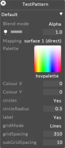
TestPattern レイヤーのプロパティ
Section titled “TestPattern レイヤーのプロパティ”Circles
Section titled “Circles”テストパターンに円を表示するかどうかを定義します。デフォルト: yes。
Circle radius
Section titled “Circle radius”円の半径を定義します。範囲: 0〜1(ステップ 0.0125)。デフォルト: 0.5。
スクリーンまたはプロジェクターのラベルをパターンの中央に表示するかどうかを定義します。ラベルの後にはスクリーンの解像度(例: 1920 x 1080)が続きます。デフォルト: yes。
Grid mode
Section titled “Grid mode”グリッドスタイルを選択します: Off または Lines。デフォルト: Lines。
Grid spacing
Section titled “Grid spacing”主要なグリッド線間の間隔(ピクセル単位)。範囲: 1〜1000。デフォルト: 100。
Sub grid spacing
Section titled “Sub grid spacing”副グリッド線(各主要グリッド正方形内の細分)間の間隔(ピクセル単位)。範囲: 1〜1000。デフォルト: 10。
Logo top left
Section titled “Logo top left”パターンの左上にレンダリングされるロゴのテクスチャスロット。デフォルトは Disguise ロゴ。
Logo bottom right
Section titled “Logo bottom right”パターンの右下にレンダリングされるロゴのテクスチャスロット。デフォルトは Disguise ロゴ。
Input Exposure
Section titled “Input Exposure”テストパターンに適用される入力露出変換(stop 単位)。利用可能な範囲はアクティブなカラーマネジメントモードによって異なります — ACES: -5〜5(ステップ 0.1)、OCIO: -10〜10(ステップ 0.1)。
Input Contrast
Section titled “Input Contrast”入力コントラスト変換。範囲: 0〜5(ステップ 0.01)。OCIO モードのみ。
Input Gamma
Section titled “Input Gamma”入力ガンマ変換。範囲: 0〜5。
Common Layer Properties
Section titled “Common Layer Properties”Brightness
Section titled “Brightness”このプロパティ(電球アイコンとして表示されます)は、レイヤー出力の明るさを制御します。
レイヤーのブレンドモードが Alpha に設定されている場合、明るさを 0 まで下げると、レイヤーの不透明度も 0 まで下がります。これは、あるレイヤーから次のレイヤーへディゾルブしたいときに便利です。その場合、新しいレイヤーを古いレイヤーの上に配置し、その明るさレベルを上げることができます。
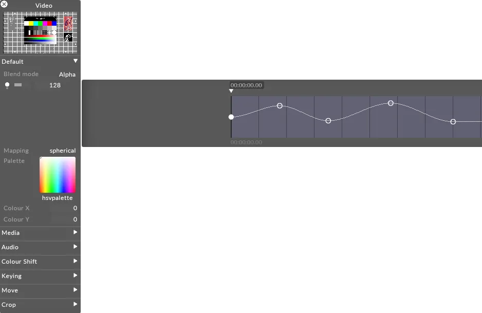
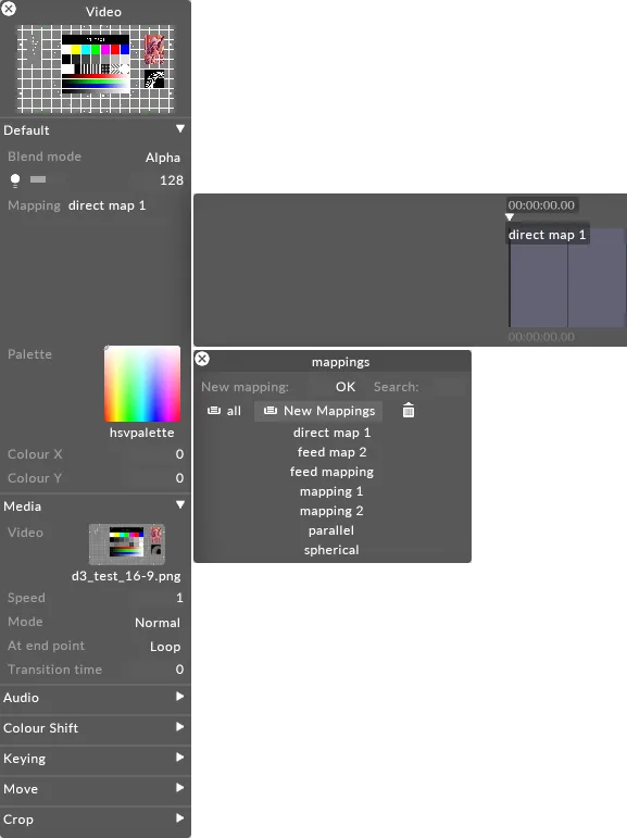
Mapping
Section titled “Mapping”Mapping プロパティは、レイヤーの出力が Stage レベルのスクリーンにどのようにマッピングされるかを制御します。
Designer が提供するさまざまなマッピングタイプの使い方を含むマッピングの詳細については、[Content Mapping] (../content/docs/ja/designer/mapping/content-mapping-overview) の章を参照してください。
Palette
Section titled “Palette”これは、ティントカラーの取得元となるビットマップを定義する静止画像ファイルを指します。デフォルトのパレット(HSVPAL)は、色相と彩度の全範囲で構成されています。このプロパティを選択すると Texture オブジェクトライブラリが開き、ローカルハードドライブの DxTexture フォルダーに保存されているすべての静止画像ファイルが表示されます。
現在のパレットビットマップ内の位置を制御し、それによって色を制御するには、xCol と yCol の値を編集する必要があります(xCol、yCol のセクションを参照)。

現在のパレットビットマップを変更するには:
- palette を左クリックして Texture オブジェクトライブラリを開きます。
- パレットビットマップに使用したい静止画像ファイルを左クリックします。
Designer で提供されている標準の静止画像以外のパレットビットマップを使用したい場合は、カスタムの静止画像ファイルを使用する必要があります。
カスタムの静止画像ファイルの配置場所と Designer でのアクセス方法については、[Placing media files] (../content/docs/ja/designer/content-management/placing-media-files) サブチャプターを参照してください。また、ファイルは [サポートされているファイル形式] (../content/docs/ja/designer/getting-started/supported-file-formats) で保存してください。
Xcol, YCol
Section titled “Xcol, YCol”これらのプロパティは、出力カラーがサンプリングされる現在のパレットビットマップ内の座標を制御します。デフォルト値は 0,0 で、(HSVPAL パレットを使用している場合)白を指します。白を選択したコンテンツの色と乗算すると、単に元のコンテンツの色が生成されます。Colour X は水平位置を制御し、0 が左端、255 が右端です。Colour Y は垂直位置を制御し、0 が上端、255 が下端です。
例えば、ビデオクリップを赤く彩度を上げるには、Colour Y の値を 255 に変更し、Colour X の値に 0 を使用します。これらの座標は、既存のコンテンツの色と乗算されているパレット内の赤色を指します。
デフォルトのパレット HSVPAL を使用している場合、Colour Y は彩度を制御し、Colour X は色相を制御します。
