OmniCal キャリブレーション
Calibration は、OmniCal Capture 中に検出された blob を使用して、カメラとプロジェクターのポーズと設定を計算する自動プロセスです。Calibration は、すべての blob から形成される一貫した 3D 点群も生成します。
OmniCal Stage Plan
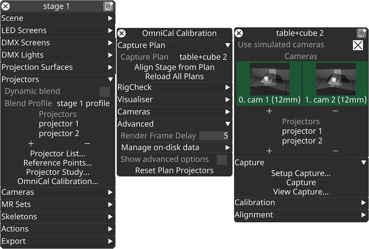
In the Stage editor, under Projectors, click OmniCal Calibration to open the Calibration editor. This widget controls the main OmniCal behaviour. Right-click on any Capture Plan to open its OmniCalStagePlan editor.
In the OmniCalStagePlan we recommend working through the sections from top to bottom: Capture, Calibration, Alignment, and Mesh Deform (if required).
Calibration
Section titled “Calibration”キャリブレーションプロセスは、キャプチャで検出された blob の位置、およびカメラとプロジェクターの相対位置とそれらのレンズ intrinsics を三角測量します。この時点から、キャリブレーションプロセスを続けるために物理ステージへのアクセスは不要になります。
Calibration Stages
Section titled “Calibration Stages”OmniCal calibration にはいくつかの段階があります。
- Camera Calibration
- カメラのポーズが、検出された blob 情報と事前キャリブレーションされたレンズデータに基づいてキャリブレーションされます。
- Camera Graph Calculation
- カメラは、相互の重なりに応じて、グラフ上で互いに接続されます。
- このグラフはプロジェクトに保存され、後の RigCheck で再利用され、整列の互換性が維持されるようにします。
- Point Cloud Reconstruction
- すべてのカメラペアが見るすべての blob から、結合された点群が生成されます。
- Projector Calibration
- プロジェクターのポーズと intrinsics が、点群と投影された blob 座標を使用してキャリブレーションされます。
- Bundle Adjustment
- 総再投影誤差を最小化することで、すべてのカメラとプロジェクターのポーズと intrinsics を最適化する反復プロセス。
- Final Point Cloud Reconstruction
Calibration 設定
Section titled “Calibration 設定”Setup Calibration… をクリックして、OmniCal Calibration Setup ウィジェットを開きます。
ほとんどの場合、デフォルト設定で十分です。良好なキャプチャ品質にもかかわらずキャリブレーション結果が不十分な場合は、その影響を明確に評価するために、一度に 1 つの設定を調整します。
デフォルトでは、より高度なキャリブレーション設定は非表示になっています。チェックボックス Show Advanced Options を有効にすると、利用可能なすべての設定が表示されます。
Redo Blob Detection
Section titled “Redo Blob Detection”Redo Blob Detection が有効になっている場合、Calibrate を押すと、通常のキャリブレーションに進む前に、まず blob detection の手順が再実行されます。
Blob detection は常に OmniCal capture の一部として実行され、その後 blob データがディスクに保存されます。Calibration は通常、新しいキャリブレーションプロセスの開始時にこの blob データを読み込みます。
Blob detection を再実行すると、ユーザーは Capture Setup の Blob Detection Settings の特定の制限を調整して、次のキャリブレーション中に効果を発揮させられます。 このワークフローで効果があるのは、Blob Area Limits などの blob フィルター設定のみです。Blob Size などの blob 投影に関連する設定は、完全な capture の再実行が必要になるため、固定されています。
Blob limits を調整してから Blob detection を再実行することは、特に以下の場合に有用な トラブルシューティング ステップになります。
- 厳しすぎる Blob limits フィルターにより、実際に使用される blob が十分でない場合。
- Blob Circularity Limits と Blob Inertia Limits を緩めると、プロジェクションサーフェス上で細長く見える blob を破棄するのを防げます。
- Blob Area Limits の最小値を調整すると、そうでなければ破棄される小さな blob を含めるのに役立ちます。
- 結果に悪影響を与える非常に大きな blob があるか、誤って多数の小さな blob に分割されている場合。この場合、より小さな Blob Area Limits の最大値を使用すると役立つことがあります。
- 結果に悪影響を与える非常に小さな blob が多数ある場合。この場合、より大きな Blob Area Limits の最小値を使用すると役立つことがあります。
Camera Calibration 設定
Section titled “Camera Calibration 設定”Camera Calibration セパレーターには、OmniCal カメラのキャリブレーションのみに影響する設定が含まれます。
ただし、カメラキャリブレーションの品質は、生成される点群、ひいてはプロジェクターキャリブレーションの品質に直接影響することに注意してください。
Camera Outlier Handling
Section titled “Camera Outlier Handling”Outlier Handling オプションは、初期のカメラキャリブレーションが、潜在的に誤った入力点(外れ値)をどう扱うかを制御します。カメラの外れ値は、反射、迷光、部分的なオクルージョンなどの外部影響によって引き起こされることがあります。外れ値検出アルゴリズムは、すべての入力点ペアの多くのサブセットを使用して、キャリブレーションを共通のコンセンサス結果から大きく逸脱させるデータを見つけます。これらの外れ値の点ペアは破棄され、それ以降の処理では無視されます。
OmniCal カメラには、以下の Outlier Handling モードが利用可能です。
- RanSaC(Random Sample And Consensus): 一般的に使用される外れ値処理アルゴリズム。
- LMedS(Least Median of Squares): RanSaC と比較してより堅牢なアルゴリズムですが、より遅いです。最大 50% の外れ値を許容します。LMedS がカメラのデフォルトです。
Desired Confidence オプションは、LMedS または RanSaC がどう機能するかを決定します。デフォルト値は 0.999 で、Disguise Support の指示がない限り変更すべきではありません。
この設定はプロジェクター用に構成されたものとは別です。Projector Outlier Handling を参照してください。
Use Camera Lens Distortion
Section titled “Use Camera Lens Distortion”Use Lens Distortion オプションは、すべての OmniCal カメラに使用される非線形レンズ歪みモデルの複雑さを決定します。各設定は、キャリブレーションプロセス(および後の Bundle Adjustment)中に、いくつのどの歪みパラメーターが計算または無視されるかを決定します。
2 つの放射状歪みパラメーターを持つレンズモデルを使用すると、barrel(樽型)と pincushion(糸巻き型)の歪みの組み合わせ(mustache(口ひげ型)歪みと呼ばれることもある)をモデル化できるため、ほとんどのユースケースで機能します。
この設定はプロジェクター用に構成されたものとは別です。Use Projector Lens Distortion を参照してください。
| レンズ歪みモード | 歪み項の数 | 歪みモデル |
|---|---|---|
| Off | 0 | None |
| radial k1 | 1 | 単純な放射状歪み(barrel または pincushion) |
| radial k1-2(デフォルト) | 2 | 典型的な放射状歪み(mix) |
| radial k1-3 | 3 | 高次の放射状歪み |
| radial k1-6 | 6 | 複雑な放射状歪み |
| radial k1 + tangential | 3 | 単純な放射状および接線方向の歪み |
| radial k1-2 + tangential | 4 | 典型的な放射状および接線方向の歪み |
| radial k1-3 + tangential | 5 | 高次の放射状および接線方向の歪み |
| radial k1-6 + tangential | 8 | 複雑な放射状および接線方向の歪み |
Calibration Model
Section titled “Calibration Model”Calibration Model は 3 つのモードのいずれかに設定できます。
- Auto(デフォルト): 適切なモデルの検出を試みます。‘Auto’ が失敗した場合にのみ、別のモードを手動で選択してください。
- Epipolar: 「深度のある」シーン、つまり blob が単に平らなサーフェスに投影されるのではなく、3 次元にわたって広がっているシーンで使用されます。
- Homography: blob がほとんど平らなサーフェスに投影されるシーン、または提供される深度が非常に浅い(例: < 1cm)シーンで使用されます。
Point Cloud Reconstruction 設定
Section titled “Point Cloud Reconstruction 設定”Point Cloud Reconstruction セパレーターには、OmniCal カメラのキャリブレーションと、それらが結合された点群にどう寄与するかに影響する設定が含まれます。
Camera graph optimisation
Section titled “Camera graph optimisation”Camera graph optimisation は、すべてのカメラが互いに重なって閉ループを形成する、つまり最初と最後のカメラが互いに重なるカメラセットアップで有効にすべきです。camera graph optimisation を有効にすると、点群の境界が出会う場所での隙間や不連続を防ぎます。これにより、ドーム、シリンダー、球、または部屋の壁の内側や上での 360 度投影の典型的なセットアップに対して、より一貫した再構成とキャリブレーション結果が得られます。
Camera graph BA iterations
Section titled “Camera graph BA iterations”Camera graph BA iterations は、camera graph optimisation のための別の Bundle Adjustment パスを制御します。デフォルトは 500 ですが、50 回を超える反復が必要になることは稀です。このステップは、カメラとプロジェクターを含む後の Bundle Adjustment ステップよりもはるかに高速です。
Projector Calibration 設定
Section titled “Projector Calibration 設定”Projector Calibration セパレーターには、プロジェクターのキャリブレーションのみに影響する設定が含まれます。
Use Projector Lens Distortion
Section titled “Use Projector Lens Distortion”プロジェクター用の Use Lens Distortion オプションは、カメラと同じ選択肢(Use Camera Lens Distortion を参照)を許容しますが、代わりにプロジェクターのキャリブレーションに適用されます。
一部の超短焦点プロジェクターレンズ(超広角)を使用する場合は、radial k1-3 や radial k1-2 + tangential などのより高いレンズ歪み設定を使用すると有益なことがあります。
Projector Outlier Handling
Section titled “Projector Outlier Handling”Outlier Handling オプションは、プロジェクターのキャリブレーションが、潜在的に誤った入力点(外れ値)をどう扱うかを制御します。プロジェクターの外れ値は通常、カメラの外れ値検出をすり抜けた不正確な点群データによって引き起こされます。詳細については Camera Outlier Handling を参照してください。
プロジェクターには、以下の Outlier Handling モードが利用可能です。
- None: あらゆる外れ値がプロジェクターのキャリブレーションに受け入れられます。入力データがクリーンであれば、これによりキャリブレーションが高速化することがあります。しかし、予期しない外れ値は、キャリブレーション品質の低下や失敗につながることがあります。
- RanSaC(Random Sample And Consensus): 一般的に使用される外れ値処理アルゴリズム。RanSaC がプロジェクターのデフォルトです。
Inlier percentage
Section titled “Inlier percentage”すべての入力点ペアに対する inlier の推定数(パーセンテージ)。
RanSaC などの外れ値処理アルゴリズムで使用されます。デフォルト値は、Disguise Support の指示がない限り変更すべきではありません。
- 単位: パーセンテージ
- 範囲: 0 - 1。デフォルト: 0.8(80%)。
Sample size
Section titled “Sample size”外れ値処理中に、入力点のサブセットを形成するためにグループ化される点ペアの数。
RanSaC などの外れ値処理アルゴリズムで使用されます。デフォルト値は、Disguise Support の指示がない限り変更すべきではありません。
- 単位: 個数
- 範囲: 6 - 1000。デフォルト: 7。
Projector Calibration Algorithm
Section titled “Projector Calibration Algorithm”Projector Calibration Algorithm は 3 つのモードのいずれかに設定できます。
- DLT(Direct Linear Transformation): 「深度のある」入力データが必要です。
- Zhang: 完全に平らな(平面の)サーフェスからの入力データでも機能します。
- Auto(デフォルト): 利用可能なすべてのアルゴリズムを試し、最良の結果を選択します。
Bundle Adjustment 設定
Section titled “Bundle Adjustment 設定”Bundle Adjustment セパレーターには、OmniCal カメラとプロジェクターのキャリブレーションパラメーターの最終最適化に影響する設定が含まれます。
Bundle Adjustment target
Section titled “Bundle Adjustment target”Bundle Adjustment target は 6 つのモードのいずれかに設定できます。
- None
Bundle Adjustment 最適化を無効にします。以前のキャプチャやキャリブレーションの段階を素早く反復するための トラブルシューティング に便利です。 - Cameras
カメラのみを最適化し、プロジェクターは初期のキャリブレーション結果のままにします。最速ですが、最高品質の投影結果は保証できません。トラブルシューティング に便利です。 - Cameras and Projectors
別々のカメラ最適化なしで、カメラとプロジェクターを結合パスで最適化します。2 台の OmniCal カメラに対して正確な結果を与えます。 - Cameras then Projectors
まずカメラを最適化し、次にカメラとプロジェクターを結合パスで最適化します。最も遅いですが、最も正確な結果を与えます。 - Cameras then each Projector
まずカメラを最適化し、次に各プロジェクターを個別のパスで最適化します。他の組み合わせモードより高速です。キャリブレーション時間を短縮するため、多数のプロジェクターに推奨されます。 - Auto(デフォルト)
カメラとプロジェクターの数に基づいて、最も適切なカメラ / プロジェクターの組み合わせを自動的に選択します。- 2 台のカメラが使用される場合、Cameras and Projectors が選択されます。
- それ以外の場合は Cameras then Projectors が選択されます。
Iterations
Section titled “Iterations”iterations(反復)の数は、全体のキャリブレーション結果を反復的に改善するのにどれだけ時間を費やすかを制御します。選択した BA target に応じて関連する、2 つの別々の iterations 設定があります。
- Iterations (combined)
- Cameras および結合された Cameras and/then Projectors モードに使用されます。
- 高い値は、特に多数のカメラとプロジェクターの場合、キャリブレーション時間を長くします。
- デフォルト: 7 回。
- Iterations (individual projectors)
- Cameras then each Projector モードに使用されます。
- このモードは高速なので、iterations を結合モードよりもはるかに高く設定できます。
- デフォルト: 14 回。
Calibration の実行
Section titled “Calibration の実行”Calibration 設定の調整が終わったら、Plan エディターで Calibrate をクリックし、「Yes」をクリックして確認すると、キャリブレーションプロセスが開始されます。 カメラとプロジェクターの数に応じて、これには数秒から数十分かかることがあります。
キャリブレーションを開始すると、その進行状況を示す新しいウィンドウが開きます。このウィンドウには、現在の キャリブレーション段階 に関する詳細なメッセージも含まれます。 キャリブレーションが完了したら、この進行状況ウィンドウを閉じられます。進行状況ウィンドウのメッセージは、後で表示するために OmniCal レポートに保存されます。
OmniCal レポート
Section titled “OmniCal レポート”OmniCal レポートは、キャリブレーションの成功と品質を評価したり、潜在的なトラブルシューティングを行ったりするのに便利です。
Open Report をクリックすると、現在の Plan または RigCheck Result のキャリブレーションの概要が表示されます。新しいウィンドウが開き、RMS 再投影誤差 やその他のメトリクスを使用してキャリブレーションの成功を詳述します。レポートには、以前のキャリブレーション進行状況ウィンドウからの詳細なメッセージも表示されます。
1 ピクセル未満の誤差値は良好とみなされ、1px を超えるものは通常、プロセス(物理セットアップ、シーン、構成など)で何かがうまくいかなかったことを示します。レポート値は、問題のあるカメラやプロジェクターの誤差をより強調するために、Green と Red の間の色で表示されます。すべてが緑であれば、キャリブレーションは成功です。
OmniCal Score
Section titled “OmniCal Score”OmniCal Score は、Plan や RigCheck の間でキャリブレーション品質を評価・比較する簡単な方法です。r32.4 で、キャリブレーションが成功したかどうか、そしてどれだけ良いかを示す「単一値」の尺度として導入されました。
OmniCal Score の基礎は、切り上げられた 集計プロジェクター RMS 誤差 に、キャリブレーション中に特定された問題に対するペナルティ項を加えたものです。これらの追加されたペナルティにより、OmniCal score は、非現実的なキャリブレーションパラメーターにもかかわらず低いことがある標準的な RMS 誤差よりも、成功の識別に役立ちます。OmniCal Score は RMS 値そのものではありませんが、同じ open-ended な範囲を使用し、0 が理論上の最良値で、1 以下の値が理想的とみなされます。
OmniCal Score には、キャリブレーション中に特定された問題に対するペナルティ項が含まれ、以下が含まれますがこれらに限りません。
- 高い RMS 誤差を持つプロジェクター。
- 無効な z-clipping 値を持つプロジェクター。
- 結果が反転しているか後ろ向きのプロジェクター。
- 非正方形のピクセルまたは歪んだ画像軸を持つプロジェクター結果。
- 非現実的な focal length、lens shift、またはレンズ歪み係数を持つプロジェクター結果。
OmniCal Score は RigCheck API のレスポンスにも含まれ、API 呼び出し元が結果を以前のものと簡単に比較できるようにします。
Camera Table
Section titled “Camera Table”このテーブルは、現在のキャリブレーションの各 OmniCal カメラを、その計算された RMS 誤差と対照して一覧表示します。また、キャリブレーションが正方形のピクセル、つまりカメラ内の単一ピクセルのアスペクト比が 1:1 になったかどうかも示します。非正方形のカメラピクセルは通常、不正確な入力データ、例えば誤ったカメラの focal length、不正確にスケーリングされた Feed Rect、または物理プロジェクターの不正確な設定の結果です。
テーブルの下には、すべてのカメラ誤差を単一の値に結合した集計カメラ RMS 誤差があり、異なるキャリブレーション間の比較を容易にします。
Projector Table
Section titled “Projector Table”このテーブルは、現在のキャリブレーションの各プロジェクターを、その計算された RMS 誤差と対照して一覧表示します。また、キャリブレーションが正方形のピクセル、つまりカメラ内の単一ピクセルのアスペクト比が 1:1 になったかどうかも示します。非正方形のプロジェクターピクセルは通常、不正確な入力データ、例えば不正確にスケーリングされた Feed Rect、または物理プロジェクターの不正確な設定の結果です。
テーブルの下には、すべてのプロジェクター誤差を単一の値に結合した集計プロジェクター RMS 誤差があり、異なるキャリブレーション間の比較を容易にします。OmniCal Score はこの値に基づきます。
Calibration と Point Cloud の可視化
Section titled “Calibration と Point Cloud の可視化”キャリブレーションが完了すると、各プロジェクターの点群とピクセル誤差を表示できます。これを行うには、OmniCal Calibration ウィジェットに移動し、Visualiser セクションを開きます。Visualisation Source を Plan に設定し、Visualisation Mode を All または Only Point Clouds に設定します。
生成された点群がステージビジュアライザーに表示されるようになります。
Point Cloud Visualisation
Section titled “Point Cloud Visualisation”Point Cloud visualisation オプションは、他の光源からの干渉やキャプチャ中の動きなどの問題を分析するのに役立つ、いくつかの可視化モードを提供します。デフォルトで最も便利なモードは ProjectorReprojError で、プロジェクターのキャリブレーション後の各投影 blob の個々の再投影誤差を可視化します。
| Point Cloud Visualisation | 説明 |
|---|---|
| Off | 点群可視化を無効にします。 |
| Observations | クラウドポイントを見るカメラペアの数を描画します。観測数は 3D 再構成に影響します: Red=0(失敗)、Blue=1(OK)、Green=2+(より良い品質)。 |
| InlierScore | クラウドポイントの inlier カテゴリを色で描画します。Red: 無効または外れ値、Orange: 外れ値、Yellow: プロジェクターキャリブレーションの外れ値、Blue: カメラキャリブレーションの外れ値、Green: inlier。 |
| InliersOnly | RanSaC や LMedS などのカメラキャリブレーション分類器を適用した後の inlier(Blue)であるクラウドポイントのみを描画します。 |
| OutliersOnly | RanSaC や LMedS などのカメラキャリブレーション分類器を適用した後の外れ値(Red)であるクラウドポイントのみを描画します。不安定な点、シーンの動きの可能性、不一致の blob コードなどを明らかにします。 |
| Deform | Mesh Deform の閾値設定を使用して、整列されたメッシュへのクラウドポイントの距離(点の法線に沿って)を描画します。 |
| ProjectorInliersOnly | プロジェクターキャリブレーション後の inlier(Blue)であるクラウドポイントのみを描画します。 |
| ProjectorOutliersOnly | プロジェクターキャリブレーション後の外れ値(Red)であるクラウドポイントのみを描画します。 |
| ProjectorReprojError | プロジェクターキャリブレーション後のクラウドポイントの再投影誤差を描画します。点の色は Green=良好、Yellow=許容、Red=不良/外れ値の間の誤差品質を示します。問題のある点や投影領域を特定するのに役立ちます。 |
Point labels
Section titled “Point labels”Point labels オプションを使用すると、各クラウドポイントにテキストラベルをレンダリングできます。テキストの内容はオプションの値に依存します。デフォルト値は Off です。
クラウドポイントのラベルをレンダリングすると、パフォーマンスに大きな影響があることに注意してください。
| Point labels | 説明 |
|---|---|
| Off | point labels を無効にします。 |
| GridCode | プロジェクターグリッド内の blob に対応する x, y インデックスを描画します。これは、OmniCal トラブルシューティングの一環として点を特定するのに役立ちます。 |
| ProjectorReprojError | プロジェクターキャリブレーション後のクラウドポイントの再投影誤差を描画します。これは点ごとの単一の RMS 誤差値で、ピクセル単位で示されます。値が低いほど良いです。1px を超える値は、特にクラスター状に現れる場合、光の干渉や動きなど、キャプチャの問題を示している可能性があります。 |
キャリブレーションの再実行
Section titled “キャリブレーションの再実行”設定を変更して Calibrate を再度クリックすると、キャリブレーションを再実行できます。なお、画像キャプチャ中に発生した問題(照明の変化、障害物など)は、Capture の再実行が必要になります。
異なる設定でキャリブレーションを再実行することは、以下の場合に便利です。
- キャリブレーション品質はまずまずだが、まだ十分に良くない場合。カメラやプロジェクターのキャリブレーション設定を微調整すると、場合によってはより良い結果を得るのに役立ちます。
- キャリブレーション設定が不正確だった場合(例: カメラキャリブレーションが「Homography」に設定されていたが、blob が非平面のサーフェスに当たる)。
- 単に設定を試すため、例えば問題をトラブルシューティングするとき。
OmniCal の制限事項
Section titled “OmniCal の制限事項”OmniCal は、特定のレンズ歪み係数を含め、プロジェクターを正確にキャリブレーションできます。内蔵ミラーを使用する場合でも、throw ratio が約 0.35 の超広角 / 超短焦点レンズを含む、あらゆる rectilinear(直線)レンズがサポートされています。
ただし、OmniCal は現在、魚眼レンズをサポートしていません。
もう 1 つの小さな制限は、OmniCal がプロジェクターレンズの色収差を補正できないことです。これは(写真と比較して)投影ではあまり一般的でない現象ですが、一部の超短焦点レンズの角で目立ちます。