OmniCal アライメント
Alignment(整列)は、キャリブレーションされたデータを Designer の座標系と整列するために必要な、ユーザー主導のプロセスです。OmniCal には、ユーザーの整列に基づいて 3D モデルの頂点を調整する ReShape 機能も含まれます。
OmniCal Stage Plan
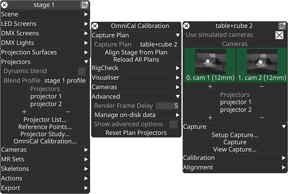
In the Stage editor, under Projectors, click OmniCal Calibration to open the Calibration editor. This widget controls the main OmniCal behaviour. Right-click on any Capture Plan to open its OmniCalStagePlan editor.
In the OmniCalStagePlan we recommend working through the sections from top to bottom: Capture, Calibration, Alignment, and Mesh Deform (if required).
Alignment
Section titled “Alignment”Alignment は、キャプチャした点群の座標系を Designer の座標系に登録(整列)するプロセスです。これは、OmniCal の calibration が完了した後、プロジェクターの出力を物理シーンに一致させるために必要なステップです。良好な整列は、Mesh Deform のような後続のステップの前提条件です。
整列を実行する
Section titled “整列を実行する”-
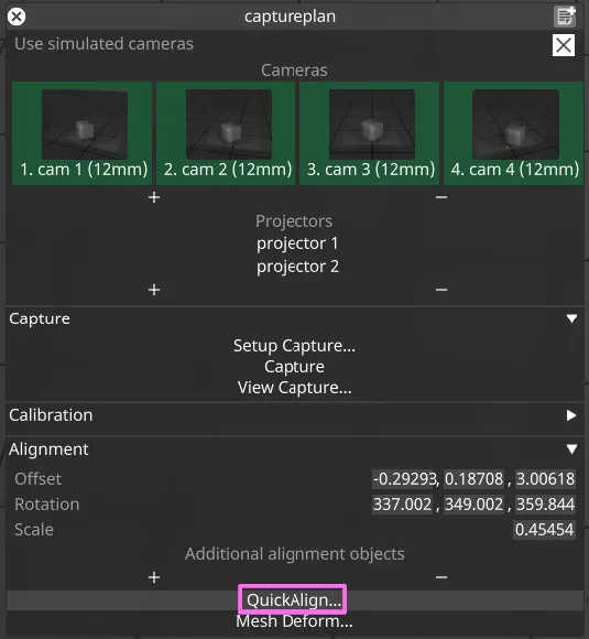
plan エディターで、Position、Rotation、Scale を介して点群の Alignment を大まかに編集します。これはまったく正確である必要はなく、後続のステップが容易になる程度に、スケールと回転の点で十分に近ければ十分です。
-
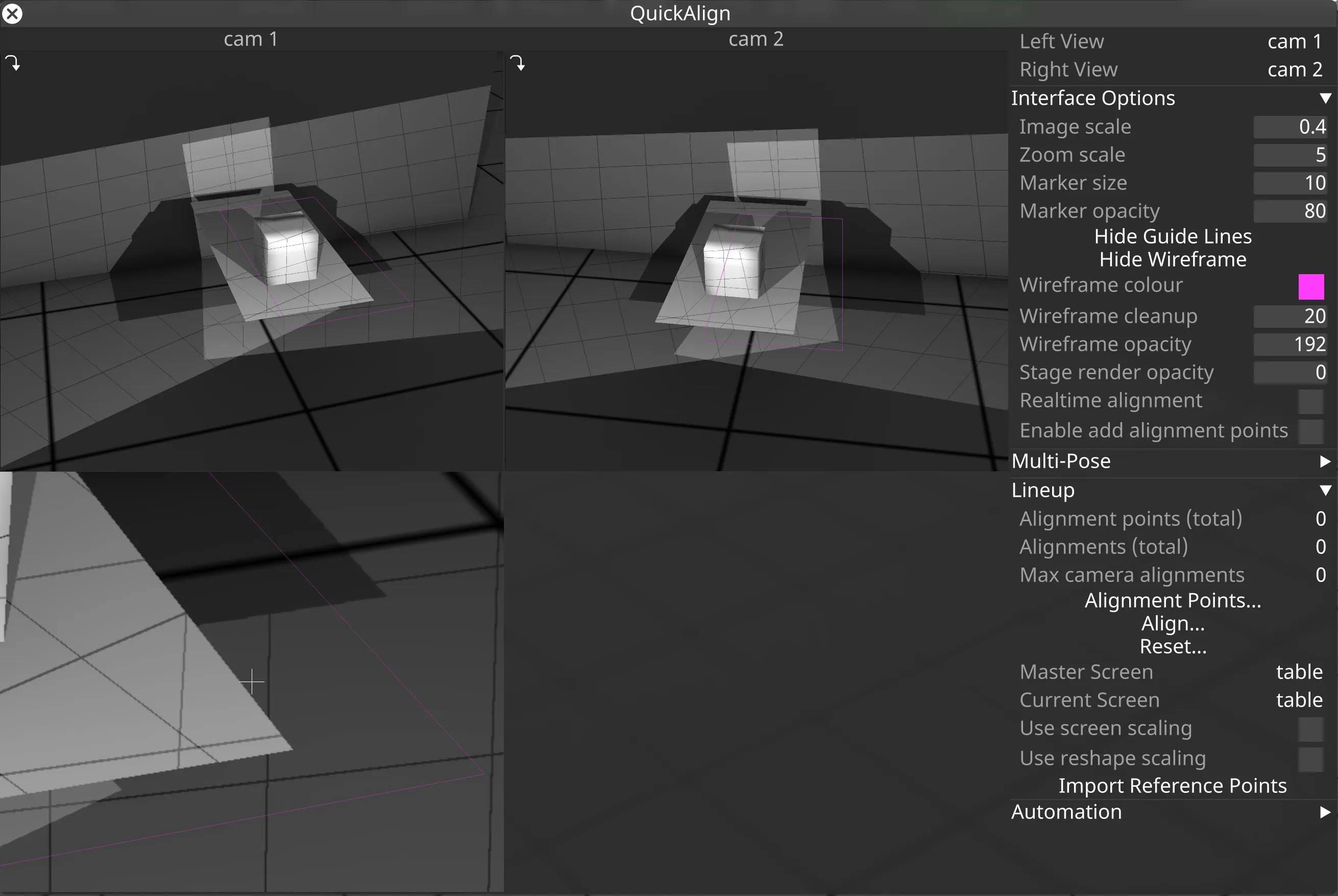
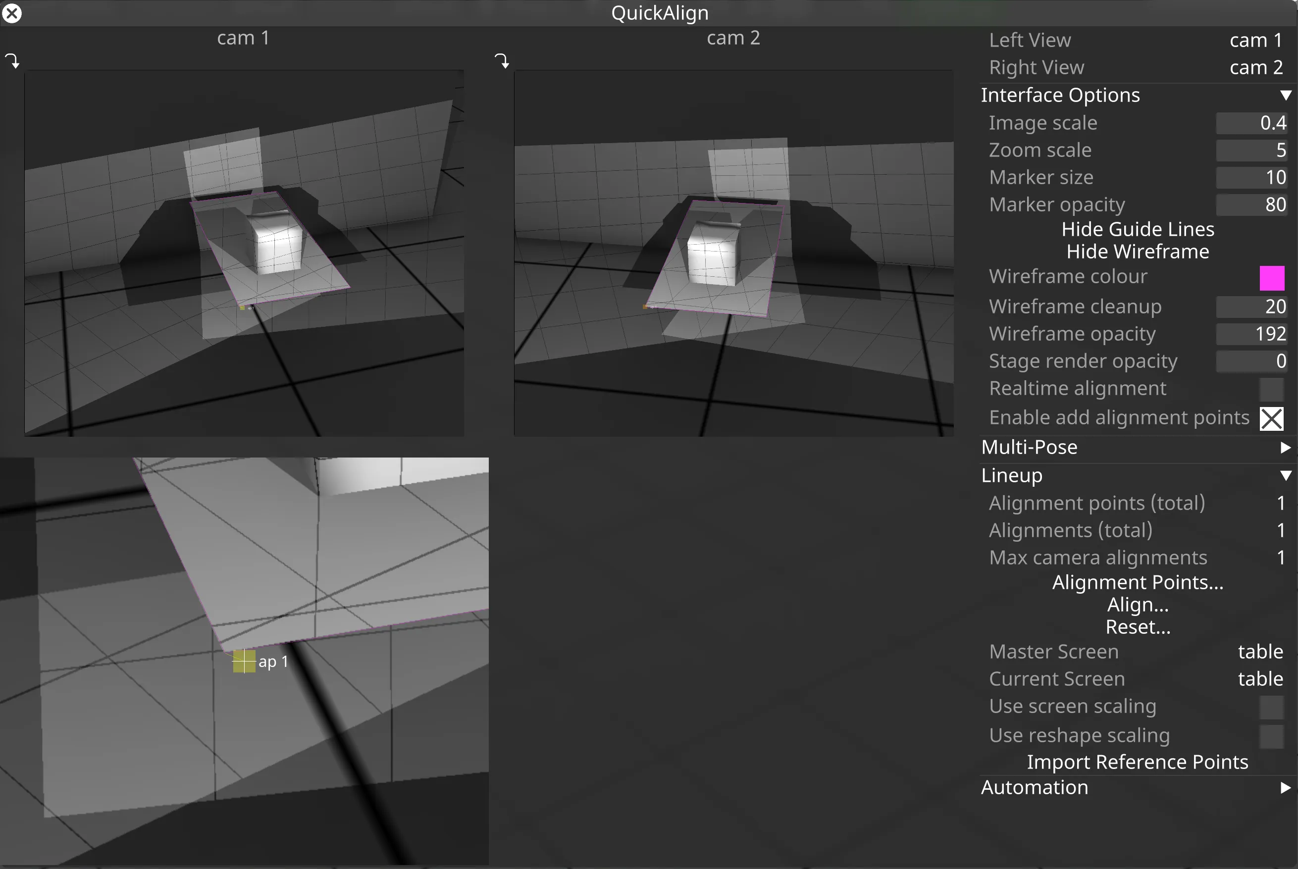
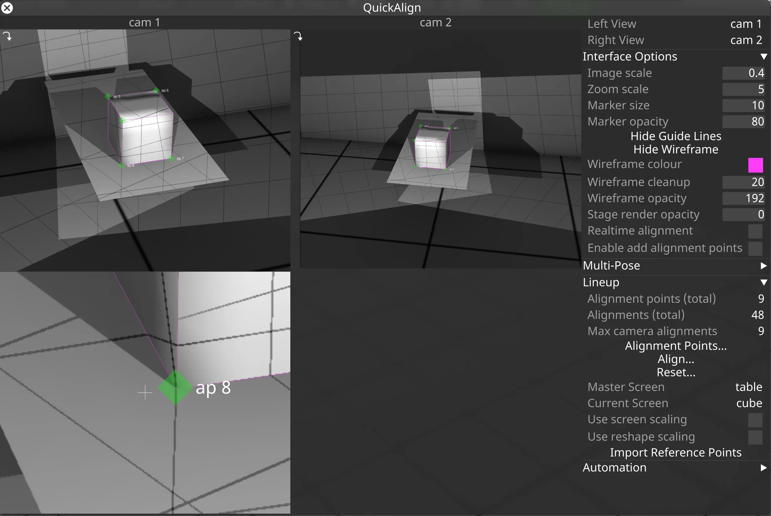
点群が大まかに整列されたら(つまり、ビジュアライザーでプロジェクションサーフェスにある程度近づいたら)、QuickAlign… をクリックして詳細な整列のためのツールを開きます。QuickAlign では、各カメラで撮影されたアライメント画像の上に描画された、最初のプロジェクションサーフェスの再投影されたワイヤーフレームが表示されるはずです。
- 上部の 2 つのビューは、右上隅で Left View と Right View として現在選択されているカメラに関連します。
- カーソルがカメラビューのいずれかにある場合、その下にズームインしたビューが表示されます。これは本質的に、カメラ画像内のピクセルへの頂点の精密な整列のための拡大鏡です。
- Interface Options では、整列プロセス中の視認性を向上させるために QuickAlign の UI 要素を調整できます。最も重要なのは、アライメントポイントマーカーのサイズ、不透明度、およびワイヤーフレームの不透明度と色を調整できることです。
-
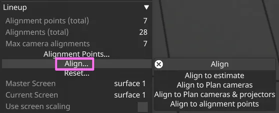
点群をステージに自動的に整列するツールがあります。QuickAlign で Align… をクリックして、整列方法のメニューを開きます。
- Align to estimate は、点群の座標とすべてのプロジェクションサーフェスの頂点に基づいて初期の整列推定を作成します。これは正確ではなく、点群とすべてのメッシュの間に良好な重なりがあり、欠けている領域や余分な領域がほとんどないことが必要です。
- Align to Plan cameras は plan カメラの位置を使用します。plan カメラの計画された位置がある程度現実的であることが必要です。
- Align to Plan cameras & projectors は plan カメラとプロジェクターの位置を使用します。plan カメラとプロジェクターの計画された位置がある程度現実的であることが必要です。
- Align to alignment points は、各カメラで手動作成されたアライメントポイントを使用します。現在のアライメントポイントデータ(下記参照)をステージに(再)適用したい場合にこのオプションを使用します。
-
ほとんどの実世界の環境では、自動 Alignment ツールは十分に良い整列を提供しません。整列を手動で改善するには、AlignmentPoints を作成し、複数のカメラでそれらを line up します。少なくとも 3 つのアライメントポイントを、それぞれ少なくとも 2 台のカメラで line up する必要があります。各カメラビューでアライメントポイントを 1 つずつ編集するのが最善です。アライメントポイントは、物理モデルの明確な特徴(例: 建物の角)に対応するメッシュの頂点に配置するのが最善です。すべてのカメラがすべてのアライメントポイントを見るわけではないので、追加のポイントが必要になることがあります。
-
AlignmentPoints を作成する:
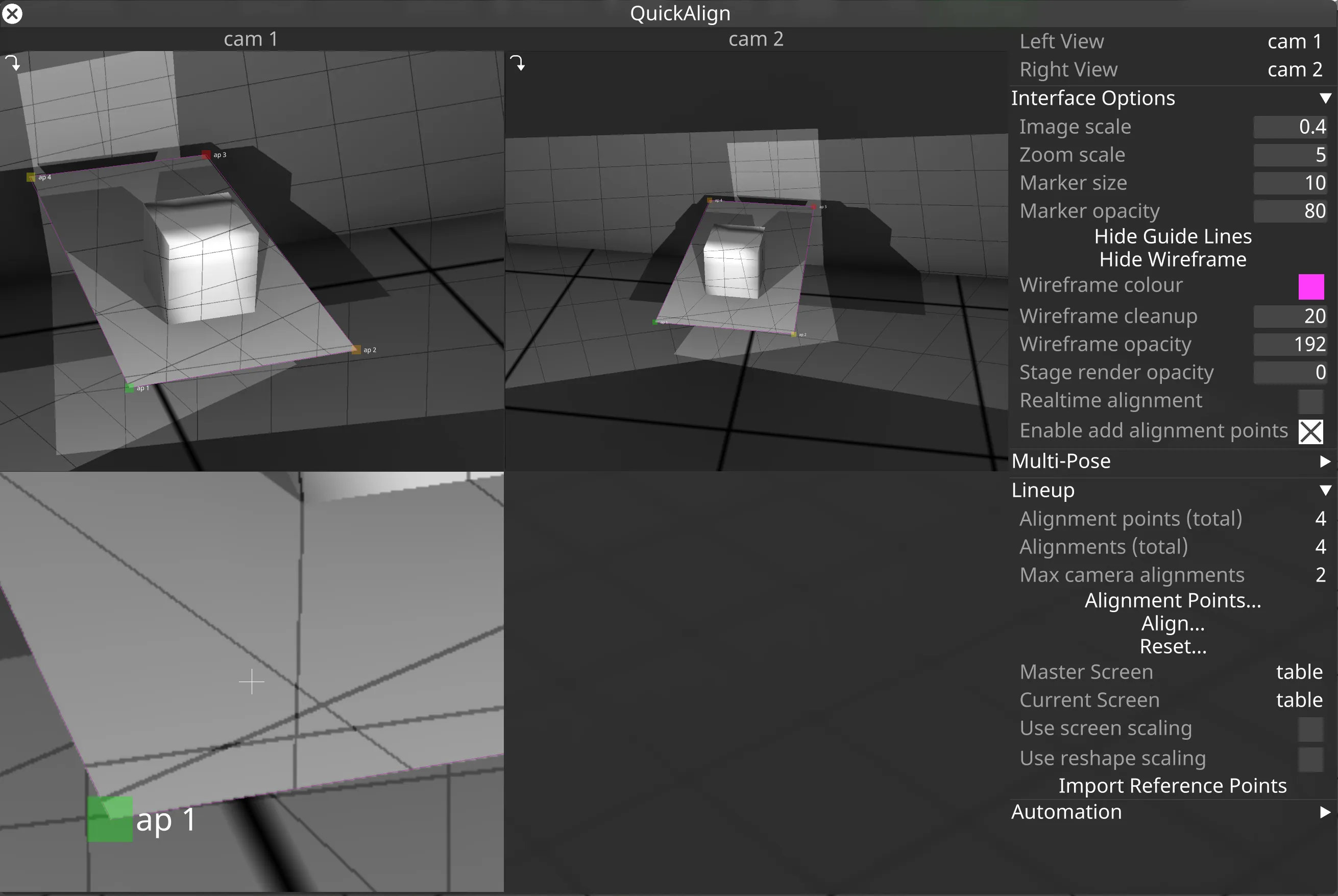
- チェックボックス Enable add alignment points を有効にします。
- ワイヤーフレーム上の頂点の近くをクリックして、このメッシュの頂点に AlignmentPoint を作成します。
- あるいは、AlignmentPoints を既存の QuickCal プロジェクターの ReferencePoints からインポートできます。
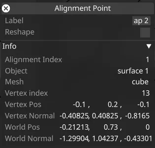
- ポイントを右クリックして、そのプロパティにアクセスして編集します。
-
AlignmentPoint をカメラ画像内の対応する領域にドラッグします。2 つ目のカメラビューの対応するポイントについても同じことを行います。
-
このプロセスを最低 3 つのポイントについて繰り返します。
- 現在選択されている AlignmentPoint は、そのマーカーが点滅します。選択されている間は、キーボードの矢印キーを使用して移動できます。
- SHIFT + 矢印キーを押すと、AlignmentPoint マーカーをより速く移動できます。
- CTRL + マウス移動で、より遅い微調整の移動ができます。
AlignmentPoint マーカーは、その整列状態に基づいて異なる色で描画されます。
- Red: このポイントは整列の一部として使用されていませんが、ビューに追加されています。
- Yellow: 現在のカメラでのみ整列されています。別のカメラで整列されるまで、整列計算には使用されません。
- Orange: 別のカメラでのみ整列されています。
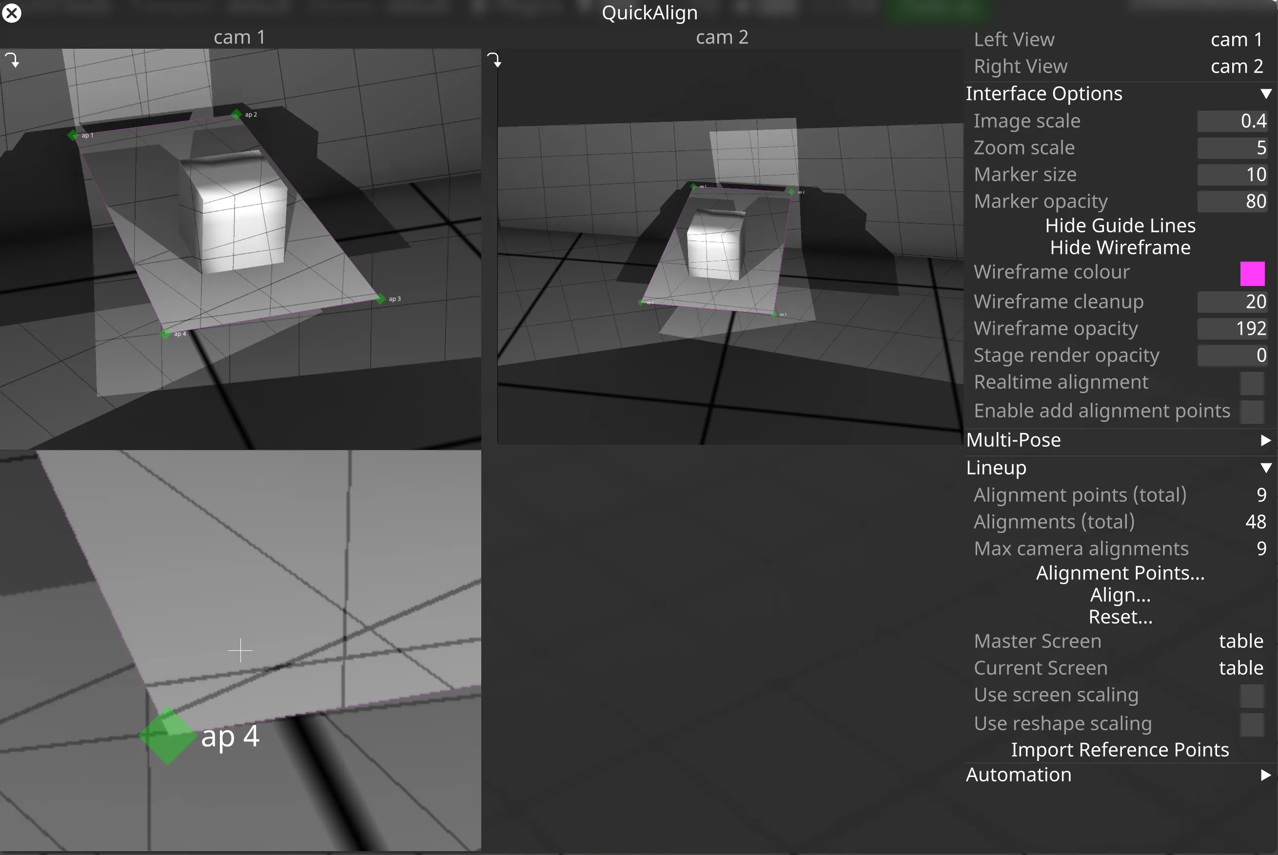
- Green: 少なくとも 2 台のカメラで整列されているため、整列計算に使用されます。
Multi-screen Alignment
Section titled “Multi-screen Alignment”plan に複数のスクリーンがある場合、Multi-screen alignment を使用すると役立つことがあります。これにより、キャプチャした画像と共通のマスタースクリーンに基づいて、ステージ内のサーフェスを整列できます。ステージ内のすべてのサーフェス間の相対的なオフセットと回転が、実際の物理サーフェスの関係に一致している場合、これは必要ないかもしれません。
- マスタースクリーンを最初に整列すべきです。
- マスタースクリーンは、他のすべてのスクリーンの登録ベースとして機能します。したがって、マスタースクリーンの reshape やスケーリングは、他のすべてのスクリーンに影響します。
- secondary スクリーンを整列すると、マスタースクリーンに対して正しい位置に移動されます。
- ステージの automation を使用して物理スクリーンの位置を制御する場合、動かないサーフェスをマスタースクリーンとして選ぶのが最善です。
複数のサーフェスを整列する方法の例は、Overview ページ のデモビデオの 約 2:40 分 で見ることができます。
Alignment Reshape
Section titled “Alignment Reshape”モデルの比率が物理サーフェスと正確に一致する場合、整列は完璧に適合するはずです。しかし、比率が正しくない場合、Alignment reshape を実行する必要があるかもしれません。Reshape では、line up されたアライメントポイントに基づいてメッシュの頂点を調整できます。これは、プロジェクションサーフェスを伸ばしたり縮めたりする調整や、一部の内部メッシュ要素(窓など)を一定量移動させるのに便利です。 典型的な用途は劇場で、シーン要素が CAD 図面に従って構築されるが、物理的な構造物が建設プロセスやステージによる制限のために若干の偏差を持つ場合です。
reshape プロセスは、キャプチャした点群を使用せず、単に既存のメッシュの頂点とメッシュの比率を調整します。これは、キャリブレーションされたカメラ、キャプチャされたアライメント画像、およびユーザーが提供したアライメントポイントデータに従って行われます。Reshape 中に頂点の UV 座標は変更されません。
Enable Reshape
Section titled “Enable Reshape”- アライメントポイントの Reshape を有効にするには、SHIFT を押しながらそれを左クリックします。 これにより、ダイヤモンドマーカー(45 度回転)で示される reshape ポイントに変わります。
- (SHIFT を押さずに)ポイントをもう一度左クリックすると、reshape されていないアライメントポイントに戻ります。
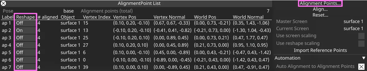
あるいは、AlignmentPoint を右クリックしてそのエディターを開き、Reshape チェックボックスを切り替えます。
AlignmentPoint List ウィジェットは、すべてのアライメントポイントの Reshape を素早く切り替える方法を提供します。
reshape ポイントの使用方法の例は、Overview ページ のデモビデオの 約 4:24 分 で見ることができます。