OCIO Layer
OCIO レイヤーは、OCIO 変換の積み重ねられたリストを最適化された方法で適用する Effect レイヤーです。サポートされているすべての OCIO 変換タイプを作成、設定、積み重ねて、必要に応じてカスタマイズされたカラーパイプラインを実現できます。
ワークフロー
Effect レイヤーは、矢印を介して他のレイヤータイプ(content または generative)からソースを受け取ります。矢印はソースレイヤーを宛先レイヤーに接続し、ソースレイヤーは宛先の Effect レイヤーに「送り込まれる(piped in)」と言われます。矢印の詳細については、[compositing layers] (../content/docs/ja/designer/layers/compositing-layers) トピックを参照してください。
2 つのレイヤー間に矢印を引くには、ALT を押しながら、ソースレイヤーから宛先レイヤーへ左クリックしてドラッグします。
- トラックに Effect レイヤーを追加します。レイヤーの追加の詳細については、[creating layers] (../content/docs/ja/designer/layers/editing-layers/creating-layers) を参照してください。
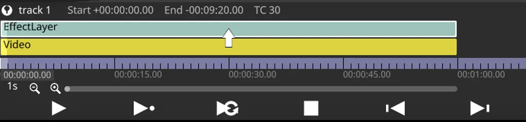
- content レイヤーから Effect レイヤーへ矢印を引き、合成順序が次の画像のようになるようにします。
- 目的の結果を得るために Effect レイヤーのプロパティを調整します。
OCIO レイヤーのプロパティ
Section titled “OCIO レイヤーのプロパティ”OCIO transforms
Section titled “OCIO transforms”カラーパイプラインを定義する OCIO 変換のリストをここで設定できます。変換の順序が重要で、下から上へ適用されます(リストの一番下が最初に適用され、一番上が最後に適用されます)。各変換は、変換名の接頭辞としてインデックス番号で順序を示し、変換タイプが接尾辞として追加されます(例: 1. myTransform [ColourTransform])。変換は Resource タイプなので、1 つ作成して他の OCIO レイヤーで再利用できます。OCIO レイヤー内で重複する OCIO 変換リソースを積み重ねることも許可されています。
InputTransform
Section titled “InputTransform”![]()
InputTransform は、選択された Input transform カラースペースから、OCIO config で現在選択されている Working space へのカラー変換を適用します(OCIO Configs を参照)。
- Input transform: 変換元のソースカラースペース。
OutputTransform
Section titled “OutputTransform”![]()
OutputTransform は、現在選択されている Working space から、OCIO config で選択された Output transform カラースペースへのカラー変換を適用します(OCIO Configs を参照)。
- Output transform: 変換先のカラースペース。
ColourSpaceTransform
Section titled “ColourSpaceTransform”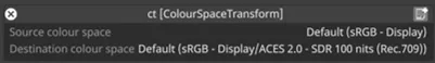
ColourSpaceTransform は、Source colour space から Destination colour space へのカラー変換を適用します。
- Source colour space: 変換元のソースカラースペース。
- Destination colour space: 変換先のカラースペース。
LookTransform
Section titled “LookTransform”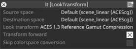
LookTransform は、OCIO config ファイルで定義された look を使って、クリエイティブなカラー変換を適用します。look は、技術的なカラースペース変換を行うのではなく、画像の外観をクリエイティブに変更します。通常は viewing transform と連携して機能します。例えば、look は VFX 作業前のフィルムスキャンに適用されるニュートラルなグレード、または監督が選んだショットごとのグレードなどです。
- Source space: 変換元のソースカラースペース。
- Destination space: 変換先のカラースペース。
- Look transform: 適用する look 変換。
- Transform forward: 有効にするとソーススペースから宛先へ変換し、無効にすると方向が逆になります。
- Skip colourspace conversion: 有効にするとカラースペース変換をスキップします。
NamedTransform
Section titled “NamedTransform”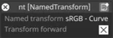
NamedTransform は、処理されるカラースペースから独立した一連のカラー変換を提供します。例えば、リファレンススペースとの間で変換する必要がないユーティリティカーブ変換などです。
- Named transform: 適用する named 変換。
- Transform forward: 有効にすると変換を順方向に適用し、無効にすると反転します。
LutTransform
Section titled “LutTransform”
LutTransform を使うと、他の OCIO 変換の間に LUT を適用できます。LUT ファイルは Designer の他の LUT と同じように見つけられます(LUT Layer を参照)。Designer の LUT Layer の従来の補間方法に加え、LutTransform はさまざまな OCIO 対応の方法を提供します。
- LUT transform: 適用する LUT。
objects/LutFileから検出されます。 - Transform forward: 有効にすると LUT を適用し、無効にすると逆 LUT を適用します。
- Interpolation: 使用する補間方法:
Nearest: 最近傍Linear: 線形補間(Lut3D の場合はトリリニア)Tetrahedra: 四面体補間(Lut3D のみ)Cubric: 3 次補間(サポートされていません)Default: デフォルトの補間タイプBest: 「最適」と思われる補間タイプ
OCIO Transforms Lists
Section titled “OCIO Transforms Lists”
OCIO 変換テーブルを使って、OCIO 変換のリストを視覚化・編集できます。カラーパイプラインを編集するために使える操作がいくつかあります。
- 変換をドラッグして順序を入れ替えます。
- 行を右クリックして OCIO 変換ウィジェットを開きます。
- フィールドを左クリックして変換要素(ソースカラースペースなど)を編集します。
- OCIO transform + をクリックして新しい OCIO 変換を追加します。
- ゴミ箱ボタン - をクリックして OCIO 変換を削除します。
Common Layer Properties
Section titled “Common Layer Properties”Blend Mode
Section titled “Blend Mode”BlendMode は、レイヤーの出力が下のレイヤーとどのように合成されるかを制御します。レイヤーは下から上の順にレンダリングされ、上にあるレイヤーは下のレイヤーの出力を変更できます。
Designer でコンテンツレイヤーの明るさ(brightness)を変更することは、実際にはそのレイヤーのアルファ値を制御しています。HAP ビデオを表示している場合でも、ソフトウェアはレイヤーごとに 1 つの制御可能なアルファのレイヤーで合成します。
画像のアルファを表現するには 2 つの方法があります。
ストレートアルファは、RGB と同じように機能するアルファチャンネルです。アルファは、ピクセルごとの 4 番目の情報チャンネルとして機能し、R・G・B が互いに独立しているのと同じように、他の 3 つのチャンネルから独立しています。例えば、ストレートアルファでは同じピクセルで RGB = 255(白)かつアルファ = 0(完全に透明)にすることができます。グラデーションレイヤーなど内部で生成されるコンテンツは、ストレートアルファで生成されます。これは 2 つのうち望ましいスタイルのアルファであり、よりクリーンな方法と考えられています。
プリマルチプライドアルファは、アルファを取り込み、ピクセルごとに RGB チャンネルの値に適用します。プリマルチプライドアルファでは、透明になるほど黒に近づきます。まるでコンテンツが黒いテーブルの上に乗っているかのようです。プリマルチプライドは Adobe Photoshop や AfterEffects のデフォルト出力です。その結果、RGB 255(完全な白)でアルファ 0 のピクセルは、最終的な画像では黒いピクセルとして計算されます。
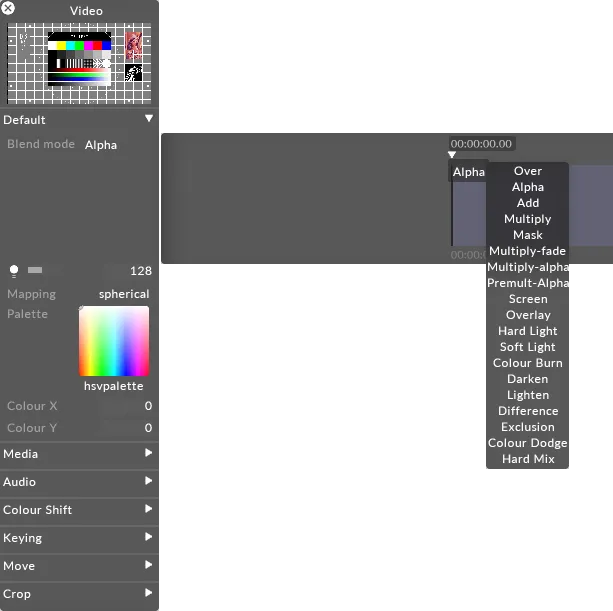
以下は、個々のブレンドモードがそれぞれ何を行うかの説明です。
Over
レイヤーを完全に不透明にします。すべてのアルファを各ピクセルの RGB 値にプリマルチプライします。アルファ = 黒なので、Over ブレンドモードのレイヤーの明るさを調整すると、暗くなります。
Alpha
デフォルトのブレンドモードです。アルファが存在する場合、アルファ値を透明度として適用します。明るさの変更により、レイヤーの透明度が増減します。
Add
各 RGB ピクセルの値を加算します。常により明るい結果になります。値は 255 で頭打ちになります。
Multiply
各サブピクセルのレベルを 0.0 から 1.0 の間のレベルとして読み取り、ソースとブレンドを乗算します。結果は常に全体的により暗い画像になります。例: 白 x グレー = 0.5。白は透明になり、黒が優先されます。アルファは Over ブレンドモードと同じ方法で適用されます。
Mask
同じマッピングを持つスタック内の上のレイヤーにマスクを適用します。詳細については Mask blending を参照してください。
Luma-Matte
このモードは、レイヤーの Rec. 709 輝度 を使って、同じマッピング内のその上のレイヤーのアルファチャンネルを制御することで、ルママットを作成します。
透明度を決定するため、システムは各ピクセルの赤・緑・青チャンネルの加重平均を計算します。この結果として得られる輝度値が、上のレイヤーの対応するピクセルのアルファ(不透明度)値としてマッピングされます。
その結果、白い領域は上のレイヤーを完全に不透明にし、黒い領域は完全に透明にし、グレーの値は比例した半透明を作成します。これは特殊な Mask ブレンドモードです。基盤となるロジックの詳細については、Mask blending を参照してください。
Inv-Luma-Matte
インバースルママットは Luma Matte マスクと同じように機能しますが、透明度が反転され、白い領域が透明になり、黒い領域が不透明になります。
Multiply-Fade
Multiply と同じですが、ソースレイヤーとブレンドレイヤーの透明度を計算するためにアルファチャンネルを利用します。最大の透明度はプリマルチプライされるため、アルファは黒になります。これはプリマルチプライによって生じる黒を無視します。
Multiply-Alpha
ストレートアルファでの Multiply です。このモードは、アルファが RGB 値にプリマルチプライされていないことを前提とし、半透明のピクセルに補正を適用しません。
Premultiply Alpha
Multiply-fade がプリマルチプライによって生じる暗化を無視するのと同様に、このブレンドモードはアルファに対して同じことを行います。
Colour Burn
コントラストを高めてベースカラーを暗くしながら、ブレンドカラーを反映するブレンドモードです。ブレンドカラーが暗いほど、ベース画像により強く色が適用されます。ブレンドカラーとして白を使用しても変化は生じません。Colour Burn ブレンドモードを使用すると、完全な不透明度で厳しい結果になることがあります。Colour Burn ブレンドモードは、レイヤーのトーンと色の調整に使用できます。
Screen
このブレンドモードは、各チャンネルの色情報を見て、ブレンドカラーとベースカラーの反転を乗算します。結果は常により明るい色になります。黒でスクリーンしても色は変わりません。白でスクリーンすると白になります。効果は複数の画像を重ねて投影するのに似ています。明るい白は完全に不透明、黒は完全に透明、50% グレーは 50% 透明です。
Overlay
ベースカラーに応じて色を乗算またはスクリーンします。パターンや色は、ベースカラーのハイライトとシャドウを保持しながら既存のピクセルにオーバーレイされます。ベースカラーは置き換えられず、元の色の明暗を反映するようにブレンドカラーと混合されます。
Hard Light
ブレンドカラーに応じて色を乗算またはスクリーンします。効果は画像に厳しいスポットライトを当てるのに似ています。ブレンドカラー(光源 / 上のレイヤー)が 50% グレーより明るい場合、スクリーンされたかのように画像が明るくなります。これは画像にハイライトを追加するのに便利です。ブレンドカラーが 50% グレーより暗い場合、乗算されたかのように画像が暗くなります。これは画像にシャドウを追加するのに便利です。純粋な黒または白でペイントすると、純粋な黒または白になります。
Soft Light
ブレンドカラーに応じて色を暗くまたは明るくします。効果は画像に拡散したスポットライトを当てるのに似ています。ブレンドカラー(光源 / 上のレイヤー)が 50% グレーより明るい場合、覆い焼きされたかのように画像が明るくなります。ブレンドカラーが 50% グレーより暗い場合、焼き込まれたかのように画像が暗くなります。純粋な黒または白でペイントすると、はっきりと暗いまたは明るい領域になりますが、純粋な黒または白にはなりません。
Darken
各チャンネルの色情報を見て、ベースカラーとブレンドカラーのうち暗い方を結果の色として選択します。ブレンドカラーより明るいピクセルは置き換えられ、ブレンドカラーより暗いピクセルは変化しません。
Lighten
各チャンネルの色情報を見て、ベースカラーとブレンドカラーのうち明るい方を結果の色として選択します。ブレンドカラーより暗いピクセルは置き換えられ、ブレンドカラーより明るいピクセルは変化しません。
Difference
各チャンネルの色情報を見て、明るさの値が大きい方に応じて、ベースカラーからブレンドカラーを、またはブレンドカラーからベースカラーを減算します。白とブレンドするとベースカラーの値が反転し、黒とブレンドしても変化は生じません。
Exclusion
Difference モードに似ていますが、コントラストが低い効果を作成します。白とブレンドするとベースカラーの値が反転します。黒とブレンドしても変化は生じません。
Colour Dodge
各チャンネルの色情報を見て、2 つの間のコントラストを下げることで、ブレンドカラーを反映するようにベースカラーを明るくします。黒とブレンドしても変化は生じません。
Hard Mix
ブレンドカラーの RGB チャンネルをベースカラーの RGB 値に加算します。あるチャンネルの合計が 255 以上になる場合は 255 の値になり、255 未満の場合は 0 の値になります。したがって、すべてのブレンドされたピクセルは 0 または 255 のいずれかの RGB チャンネルを持ちます。これにより、すべてのピクセルが原色(RGB)、白、または黒に変化します。
Brightness
Section titled “Brightness”このプロパティ(電球アイコンとして表示されます)は、レイヤー出力の明るさを制御します。
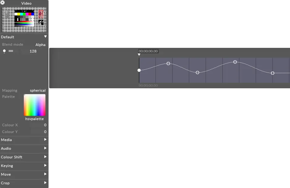
レイヤーのブレンドモードが Alpha に設定されている場合、明るさを 0 まで下げると、レイヤーの不透明度も 0 まで下がります。これは、あるレイヤーから次のレイヤーへディゾルブしたいときに便利です。その場合、新しいレイヤーを古いレイヤーの上に配置し、その明るさレベルを上げることができます。
Mapping
Section titled “Mapping”Mapping プロパティは、レイヤーの出力が Stage レベルのスクリーンにどのようにマッピングされるかを制御します。
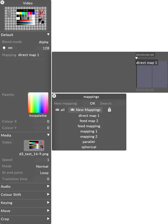
Designer が提供するさまざまなマッピングタイプの使い方を含むマッピングの詳細については、[Content Mapping] (../content/docs/ja/designer/mapping/content-mapping-overview) の章を参照してください。